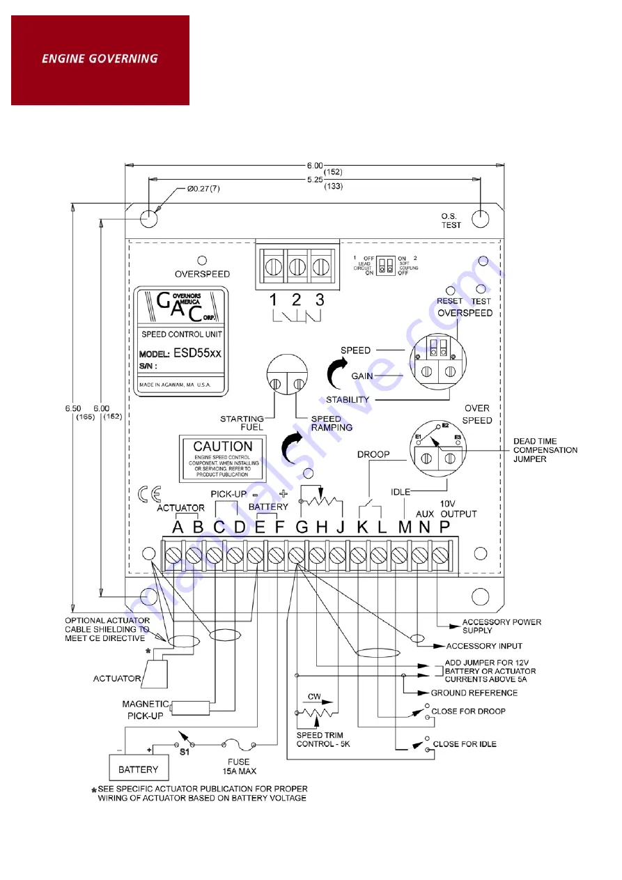
background image

Technical Information 

Diagramm2 for ESD-5550, ESD-5555 and ESD-5570 only 

Summary of Contents for ESD-5550 Series

Page 1: ...a control cabinet or engine mounted enclosure with other dedicated control equipment If water mist or condensation may come in contact with the controller it should be mounted vertically This will al...

Page 2: ...he speed sensor 3 4 turn after touching the ring gear teeth will achieve a satisfactory air gap The magnetic speed sensor voltage should be at least 1 VAC RMS during cranking ADJUSTMENTS Before Starti...

Page 3: ...peed function is now set to approximately 10 above the requested speed If a different value of overspeed setting is required raise the engine speed to the desired overspeed value i e 115 Rotate the OV...

Page 4: ...s method separates the starting process so that each may be optimized for the lowest smoke emissions Remove the connection between Terminals M G Start the engine and adjust the SPEED RAMPING for the l...

Page 5: ...Terminals N and P This is required to match the voltage levels between the speed control unit and the synchronizer When an accessory is connected to Terminal N the speed will decrease and the speed a...

Page 6: ...Hz 1K 2 400 Hz 5K 3 000 Hz 10K 3 500 Hz 25K 3 700 Hz 50K Select Proper Potentiometer Value from Table 4 SPECIFICATIONS PERFORMANCE Isochronous Operation Steady State Stability 0 25 or better Speed Ran...

Page 7: ...d N C 10 Amps RELIABILITY Vibration 1G 20 100 Hz Testing 100 Functionally Tested PHYSICAL Dimensions See Outline DIAGRAM 1 Weight 1 8 lbs 820 grams Mounting Any Position Vertical Preferred Droop is ba...

Page 8: ...Technical Information Diagramm2 for ESD 5550 ESD 5555 and ESD 5570 only...

Page 9: ...Technical Information Diagramm for ESD 5556 only...

Page 10: ...s A F on the speed control unit 1 If the voltage speed reading is 1 0 to 2 0 VDC a SPEED adjustment is set above desired speed b Defective speed control unit 2 If the voltage reading is above 2 0 VDC...

Page 11: ...ing may require to be a special EMI class shielding For these conditions contact for specific recommendations Instability Instability in a closed loop speed control system can be categorized into two...

Page 12: ...rect for disturbance Look for engine misfirings an erratic fuel system or load changes on the engine generator set voltage regulator If the throttle is slightly erratic but performance is fast move sw...

Reviews: