background image

5

Governors America Corp. © 2020 Copyright All Rights Reserved

ESD5550-5570 Series Speed Control Unit


9-2020-E


PIB1003

5

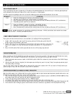
ADJUSTMENTS 

Before starting the engine, check and/or adjust the potentiometer and following settings as desired. 

Before STarTInG THe enGIne

The speed control unit governed speed setting is factory set at approximately engine idle speed 1000 Hz., speed sensor signal).

Crank the engine with DC power applied to the governor system. The governor system should control the engine at a low idle speed. If the 

engine is unstable after starting, turn the GAIN and STABILITy adjustments CCW until the engine is stable.

STarTInG THe enGIne

The overspeed relay output terminals offer both normally open and normally closed contacts.

1.  When the engine is running at the desired speed, push and hold the TEST button. 

2.  Rotate the OVERSPEED adjustment CCW until the red OVERSPEED LED lights and the 

relay energizes. Current to the actuator will be removed and the engine will shut off.

3.  Release the TEST button. 

4.  After the engine stops, press the RESET button or remove battery power. 

5.  Restart the engine and it will return to the original speed setting. 

The overspeed function is now set to approximately 10% above the requested speed.

1 2

ON

STABILITY

GAIN

SPEED

OVERSPEED

aDJUSTInG overSPeeD

aDJUSTmenT / SWITcH

PoTenTIomeTer / SWITcH

facTorY SeTTInG

noTeS

SPEED

25 turn

1470 Hz ± 50 Hz w/ min. trim

GAIN

270° turn

50%

Middle position

STABILITy

270° turn

50%

Middle position

DROOP

270° turn

0% (CCW)

IDLE

270° turn

1075± 75 Hz

STARTING FuEL RAMP

270° turn

100% (CW) Maximum Fuel

SPEED RAMP

270° turn

0% (CCW) Fastest

OVERSPEED

25 turn

100% (CW) Highest

SW1 Lead Circuit

switch

ON

SW2 Soft Coupling

switch

OFF

The engine’s exhaust smoke at start-up can be minimized by completing the following adjustments:

1.  Place the engine in idle by connecting Terminals M & G.

2.  Adjust the IDLE speed for as low a speed setting as the application allows.

3.  Adjust the STARTING FuEL CCW until the engine speed begins to fall. Increase the STARTING FuEL slightly so that the idle speed 

is returned to the desired level.

4.  Stop the engine.

 STarTInG fUeL aDJUSTmenT

IDLe SPeeD SeTTInG

If the IDLE speed setting was not adjusted as detailed in Starting Fuel Adjustment section, then complete the following:

1.  Place the optional external selector switch in the IDLE position. 

2.  Adjust the IDLE CW yo increase the idle speed set point. 

3.  When the engine is at idle speed, the speed control unit applies droop to the governor system to ensure stable operation.

Summary of Contents for ESD-5550 Series

Page 1: ...er DNV GL Bureau Vertas PHYSICAL Dimension See Section 3 Installation Weight 1 8 lbf 0 82 kgf Mounting Any position vertical preferred The ESD5550 5570 series speed control unit is an all electronic device de signed to control engine speed with fast and precise response to transient load changes This closed loop control when connected to a proportional electric actuator and supplied with a magneti...

Page 2: ...ed Control Unit 9 2020 E PIB1003 3 Installation Mount in a cabinet engine enclosure or sealed metal box Vertical orientation allows fluids to drain in moist environments Dimensions Avoid extreme heat in mm Take into account the following preferences when mounting the speed controller ...

Page 3: ...1003 4 Wiring An overspeed shutdown device independent of the governor system must be provided to prevent loss of engine control which may cause personal injury or equipment damage Do not rely exclusively on the governor system to prevent over speed A secondary shutoff device such as a fuel solenoid must be used ...

Page 4: ...sure no other part of the shield comes in contact with engine ground otherwise stray speed signals may be introduced into the speed control unit With the engine stopped adjust the gap between the magnetic speed sensor and the ring gear teeth The gap should not be any smaller than 0 020 in 0 45 mm Usually backing out the speed sensor 1 4 to 1 2 turn after touching the ring gear teeth will achieve a...

Page 5: ...g The overspeed function is now set to approximately 10 above the requested speed 1 2 ON STABILITY GAIN SPEED OVERSPEED ADJUSTING OVERSPEED ADJUSTMENT SWITCH POTENTIOMETER SWITCH FACTORY SETTING NOTES SPEED 25 turn 1470 Hz 50 Hz w min trim GAIN 270 turn 50 Middle position STABILITY 270 turn 50 Middle position DROOP 270 turn 0 CCW IDLE 270 turn 1075 75 Hz STARTING FUEL RAMP 270 turn 100 CW Maximum ...

Page 6: ...obtained with an optional 5K Speed Trim Control See section 4 Wiring diagram Once the engine is at operating speed and at no load the following governor performance adjustment can be made PARAMETER PROCEDURE GAIN 1 Rotate the GAIN adjustment clockwise until instability develops 2 Gradually move the adjustment counterclockwise until stability returns 3 Move the adjustment one division further count...

Page 7: ...t governs well with 0 5 volts RMS speed sensor signal A speed sensor signal of 3 volts RMS or greater at governed speed is recommended Measurement of the signal is made at Terminals C and D The amplitude of the speed sensor signal can be raised by reducing the gap between the speed sensor tip and the engine ring gear The gap should not be any smaller than 0 02 in 0 5 mm When the engine is stopped ...

Page 8: ... governor system After the actuator goes to full fuel disconnect the speed sensor at Terminal C D If the actuator is still at full fuel speed then the speed control unit is defective 2 Manually hold the engine at the desired running speed Measure the DC voltage between Terminals A F on the speed control unit 1 If the voltage reading is 1 0 to 2 0 V DC SPEED adjustment is set above desired speed De...

Reviews: