background image

REV. 3/15 


GB731 S/N: 1702 AND ABOVE  

PLEASE CONTACT GAGE BILT FOR ALL OTHER SERIAL NUMBERS. 

FILLING AND BLEEDING INSTRUCTIONS 


NOTE:


Fill bottle Assy (745163) is required. 


WARNING: 

Do not cycle tool without fill bottle assy (745163), or the button head cap screw (402482) and stat-o-seal (S572), 


 installed in the head cylinder (731298). Severe personal injury may result. 


CAUTION: 

Before filling handle assy (722132), the air piston assy (704121) should be all the way down.


CAUTION: 


When forcing piston rod assy (731333) downward with head cylinder (731298) removed, hydraulic oil will eject 


forcibly from handle assy (722132). 


CAUTION:


Use CAUTION when removing button head cap screws (402482), stat-o-seals (S572) and 4oz fill bottle assy (745163). Hydraulic oil 


  may be under pressure.


WARNING:


Failure to follow these instructions carefully may result in severe personal injury.


To replace a small amount of oil in the tool, cycle tool to rear position disconnect air and follow steps 6-16 below.  


Should it become necessary to completely refill the tool (as would be required after tool has been dismantled and reassembled), take 
the following steps.  


1. Remove four button head cap screws (A-928). Remove head cylinder (731298) from handle assy (722132). Ensure air piston assy 
  (704121) is at the full bottom of stroke by pushing power piston rod assy (731333) down.  


2. Fill power cylinder (731237) and oil passage (hole for o’ring S832 ) to the top, being careful not to get oil into the air passage.  


3. Place gasket (704129) and o'ring (S832) on top of the handle assy (722132).  


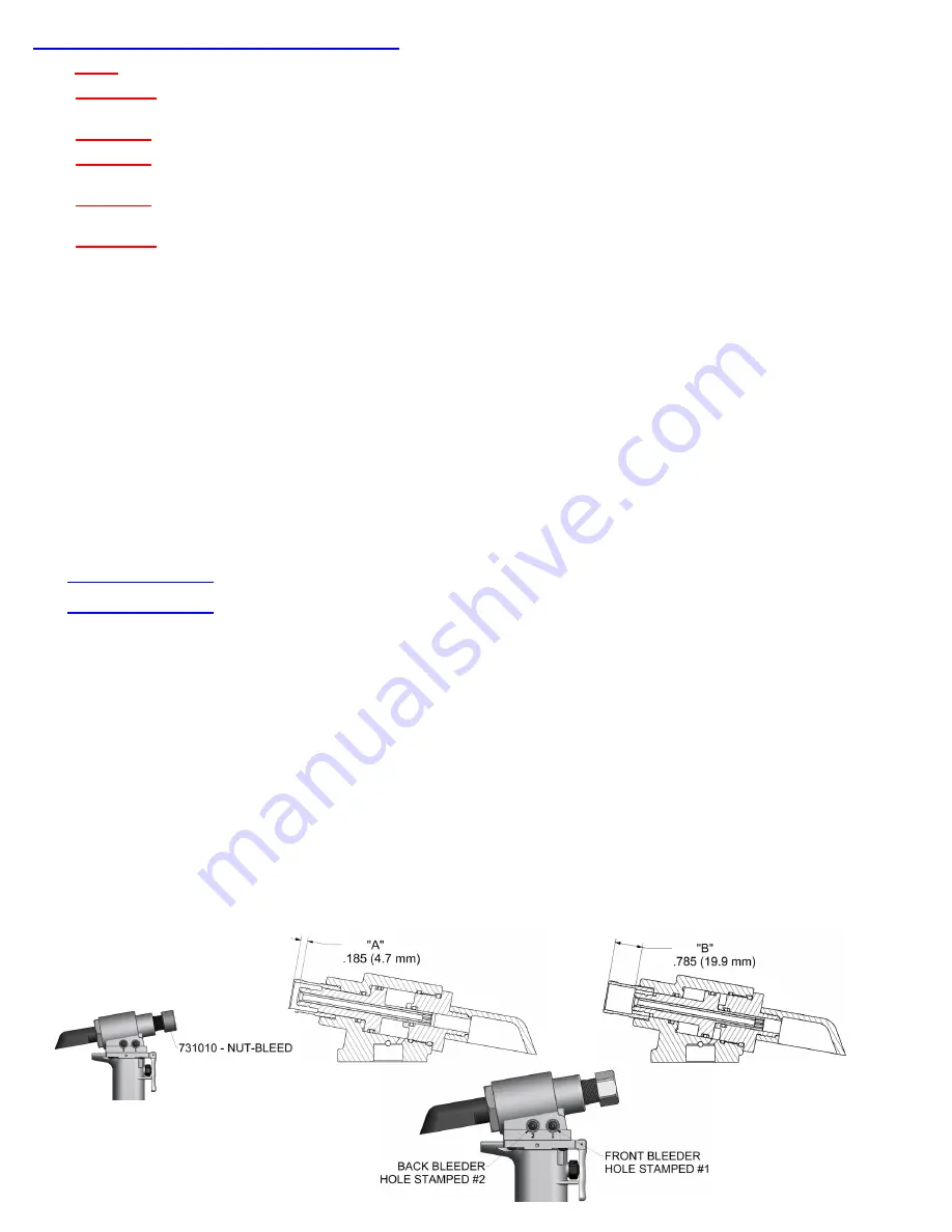
4. Push piston (731211) to rear of head cylinder (731298) until it stops. (DIM “B”)  


5. Press head cylinder (731298) down on top of handle assy (722132), being careful not to tear o'ring (403773) on top of power cylinder 
  (731237), install button head cap screws (A-928) and tighten evenly to 40 inch lbs.  


6. Lay tool down on its side with bleeder screws facing up. Carefully remove the front button head cap screw (402482) and stat-o-seal 
  (S572) from hole stamped #1 on side of head cylinder (731298). Attach fill bottle assy (745163) making sure button head cap  screw 
  (402482) and stat-o-seal (S572) are in place on hole stamped #2. 

(NOTE: Front hole stamped #1 could be under pressure.) 


7. Connect tool to air supply. Piston (731211) will then move to forward position. See (DIM “A”). Cycle tool ten times.  


8. Disconnect air supply. Check “A” dimension.  


If “A” dimension checks  

within specifications,  proceed to step 9. 


If “A” dimension checks  

long,  remove (211102) nut and (240102) retaining nut stop from (752301) nose fitting, thread bleed nut 


(731010) (Sold Separately) onto piston (731211) until snug, bringing piston (731211) full forward to “A” dimension. Remove bleed nut  (731010). 


9.  Remove fill bottle assy (745163) and replace button head cap screw (402482) and stat-o-seal (S572) on front hole (stamped #1) of head cylinder 
  (731298) and torque 35-40 inch lbs.   


10. Connect air supply and cycle tool to rear position.  While depressing actuator lever assy, disconnect air supply, with piston in “B” position.  


11. Carefully remove the back button head cap screw (402482) and stat-o-seal (S572) from hole stamped #2 on side of head cylinder 
 

(731298). Attach fill bottle assy (745163) making sure button head cap screw (402482) and stat-o-seal (S572) are in place on hole 


stamped #1. 

NOTE: Back hole stamped #2 could be under pressure. ) 


12. Connect tool to air supply. Cycle tool ten times until no air rises in the bottle.  


13. Disconnect air supply. Remove (211102) nut and (240102) retaining nut stop from (752301) nose fitting. Thread bleed nut  (731010) 
 

(Sold Separately) onto piston (731211) until snug, bringing piston full forward to “A” dimension.   


14. Remove fill bottle assy (745163) and replace button head cap screw (402482) and stat-o-seal (S572) on back hole (stamped #2) of 
 

head cylinder (731298)  and torque 35-40 inch lbs. Remove bleed nut  (731010). 


15. Connect tool to air supply and cycle tool ten times.  


16. Check stroke of .600” (15.2 mm) (see below). We recommend using dial calipers. With the actuator lever assy (704343) released 
 

check dimension (A). Holding actuator lever assy (704343) in, check dimension (B). Subtract dimension (A) from dimension (B). If 


stroke is not consistent within 1/64" (.0156) repeat steps 6-16. 

(731010 Sold Separately)


Summary of Contents for 1702

Page 1: ...4766 Centre Court 586 226 1500 Clinton Twp MI 48038 586 226 1505 Fax e mail solutions gagebilt com www gagebilt com GAGE BILT TOOLS ARE AVAILABLE WORLDWIDE E MAIL US FOR A DISTRIBUTOR NEAR YOU S N 1702 AND ABOVE PLEASE CONTACT GAGE BILT FOR ALL OTHER SERIAL NUMBERS ...

Page 2: ...c Transmission Oil Dexron III or equivalent Setting stroke 600 15 24 mm Rated pull load 4 800 lbs 21 35 kN Noise level 81 5 dB A Vibration Tested No Hazards Found TABLE OF CONTENTS Description Page Warnings 3 Principle of Operation 4 How to use the GB731 5 Description and Maintenance 6 Filling and Bleeding 7 Troubleshooting 8 Overhaul 9 Parts Lists 10 11 DEXRON III Oil Safety Data 12 Nose Assembly...

Page 3: ...e personal injury may result WARNING It is required to use hearing protection A test was carried out in a simulated work environment where the background level was 73 2 dB A In this condition the max level was 81 5 dB A Therefore it is required where prolonged use hearing protection be used CAUTION Do not use beyond the design intent WARNING Tool must be maintained in a safe working condition at a...

Page 4: ...ds and moves through the ports in the bottom of the power cylinder 7 up into the port in the handle assy 6 and then up into the head cylinder 2 4 The hydraulic oil pushes the piston 1 backwards while the internal components of the attached nose assembly are also moving with the piston to start the fastener installation thus transferring 4 800 lbs 21 35 kN of pulling force on the nose assembly and ...

Page 5: ...plug from Swivel A 249 and screw in your air fitting 2 Attach Deflector 752122 to rear of End Cap 731417 located on rear of Head Cylinder 731298 WARNING Rotate deflector away from operator and other persons working in the vicinity 3 Connect air hose to tool 3 8 minimum diameter air line is mandatory 90 p s i 6 2 bar is recommended and cycle tool ten times by depressing and releasing actuator lever...

Page 6: ...aner lubricant follow in structions below 1 Disconnect tool vacuum line if equipped 2 Point nose assembly into oil as shown 3 Cycle tool 8 10 times and wipe dry MAINTENANCE WARNING Maintenance personnel MUST read and understand all warnings and cautions WARNING Disconnect tool from its power source before performing maintenance WARNING Excessive contact with hydraulic oil and lubricants should be ...

Page 7: ...on side of head cylinder 731298 Attach fill bottle assy 745163 making sure button head cap screw 402482 and stat o seal S572 are in place on hole stamped 2 NOTE Front hole stamped 1 could be under pressure 7 Connect tool to air supply Piston 731211 will then move to forward position See DIM A Cycle tool ten times 8 Disconnect air supply Check A dimension If A dimension checks within specifications...

Page 8: ...be blocked or damaged Hole diameter should be 028 Clear and size or replace 3 NO OPERATION WHEN ACTUATOR LEVER ASSY 704343 IS DEPRESSED a Tool seized due to mechanical failure or damaged parts 4 OIL LEAKAGE a DO NOT OPERATE WITH OIL LEAKING FROM TOOL HIGH PRESSURE OIL MAY CAUSE SEVERE PERSONAL INJURY b Any oil leaking externally should be traced to its source An o ring or seal that leaks should be...

Page 9: ...use of Service Kit 731006 which contains a complete set of o rings back up rings screws washers and gasket A 1395 T HANDLE WRENCH 704151 POWER CYLINDER TOOL 704152 SEAL GUIDE 704150 PACKING PLUG WRENCH 704162 VALVE SPRING INSTALLATION TOOL 704163 VALVE SPRING REMOVAL TOOL S1178 VALVE EXTRACTOR 745163 FILL BOTTLE ASSEMBLY 704214 CATCHER BAG NOT SHOWN IS SOLD SEPARATELY Part No Description A 1395 T ...

Page 10: ...d cap 731417 Push against threaded end of piston 731211 to slide it out of head cylinder 731298 Be careful not to damage threads or cause burrs on polished piston 731211 surface The re assembly sequence is the opposite of disassembly See Filling and Bleeding instructions Apply Loctite 242 and torque the four button head cap screws A 928 uniformly to 40 inch lbs to prevent leakage around the gasket...

Page 11: ...into top of power cylinder 731237 and into slot of piston rod assy 731333 While holding this wrench remove flexlock nut 400559 using a 7 16 socket wrench Still holding piston rod wrench A 1395 remove air piston assy 704121 using packing plug wrench 704150 by turning counterclockwise When air piston assy 704121 is completely free from piston rod assy 731333 tap or push on the piston rod wrench A 13...

Page 12: ...ds will be evolved when this material undergoes combustion ACCIDENTAL RELEASE MEASURES Protective Measures Eliminate all sources of ignition in vicinity of spilled material Spill Management Stop the source of the release if you can do it without risk Contain release to prevent further contamination of soil surface water or groundwater Clean up spill as soon as possible Use appropriate techniques s...

Page 13: ... 713 20 SB08 713 45 SB08 713A 58RA SB08 204D 27OS SB08 204D 37OS 1 8 UAB04 752A 43OS 5 32 UAB568 713 21 4 UAB568 713 61 4 3 16 UBB06 751B 54RA 5 UBB06 752A 43OS 1 4 UAB08 204D 27OS UAB08 204D 37OS 1 8 SMLS04 752C 20 SMLS04 752C 45 SMLS04 751B 54RA 5 SMLS04 752A 43OS 5 32 SMLS05 752C 20 SMLS05 752C 45 SMLS05 751B 54RA 5 SMLS05 752A 43OS 3 16 SMLS06 752B 20 SMLS06 752B 45 SMLS06 751B 54RA 5 SMLS06 7...

Page 14: ...r no circumstances will the seller be liable for incidental or consequential damages or for damages incurred by the buyer or subsequent user in repairing or replacing defective goods or if the goods covered by this warranty are reworked or subjected to any type of additional processing This warranty is void if Seller is not notified in writing of any rejections or defects within 6 months after the...

Reviews: