background image


9/11 REV. 7/13 

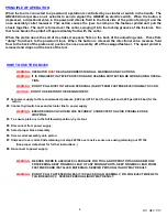
PRINCIPLE OF OPERATION


When the tool is connected to a powerunit, operation is controlled by a actuator or switch in the handle.  The 
GB2480A incorporates an air actuator to send a signal; the GB2480 an electric switch.  When the button is 
depressed, a directional valve in the powerunit directs fluid to the front side of the piston forcing it and the 
nose  assembly  collet  rearward.    This  action  causes  the  jaws  to  clamp  on  the  fastener  pintail  and  pull  the 
sheets together.  The anvil is forced over the collar, swaging it into the locking grooves of the fastener.  Fur-
ther force breaks the pintail off, approximately flush with the collar. 
 
When the piston nears the end of its stroke it exposes flats on the back of the unloading valve.  These flats 
"dump"  fluid  back  to  the  powerunit  tank.    When  the  button  is  released  the  directional  valve  reverses  fluid 
flow to the back of the piston and pushes the nose assembly off of the swaged fastener.  The spent pintail is 
released and drops out the back of the tool. 

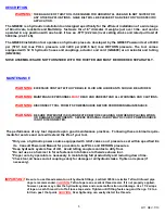
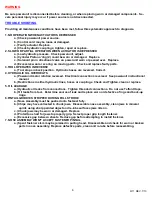
HOW TO USE THE GB2480 

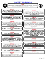
WARNING: 


OPERATOR 

MUST 

READ AND UNDERSTAND ALL WARNINGS AND CAUTIONS. 

WARNING: 


IT IS REQUIRED THAT EYE PROTECTION AND HEARING PROTECTION BE WORN DURING OPERA-

TION. 

WARNING: 


DO NOT PULL RIVET IN THE AIR. PERSONAL INJURY FROM FASTENER EJECTING MAY OCCUR. 

CAUTION: 


DO NOT USE BEYOND THE DESIGN INTENT. 


#1. Set power supply to the recommended pressure, 8,400 psi (579.1 bar) for the pull and 3,200 psi (220.6 bar) for the 


return.  


#2. Connect hydraulic hoses and actuator line to power supply. 


WARNING: 

 ENSURE HYDRAULIC HOSES ARE SECURELY CONNECTED TO AVOID POSSIBLE HOSE  


WHIPPING.  


#3.  To ensure piston is in the full forward position, Cycle tool. 


#4.  Disconnect from power supply. 


#5.  Select proper Nose Assembly 


#6.  Screw collet assembly onto piston. 


#7.  Slide anvil over collet. Slide retaining nut stop 240102 over anvil, secure nose using retaining nut 211102 


(See proper data sheet for further instructions.) 


#8. Re-connect to power supply.  


WARNING: 

 BE SURE THERE IS ADEQUATE CLEARANCE FOR TOOL AND OPERATOR’S HANDS BEFORE 


PROCEEDING. KEEP FINGERS CLEAR OF ANY MOVING PARTS. KEEP FINGERS CLEAR FROM 


FASTENERS AND INSTALLED MATERIALS. SERVIER PERSONAL INJURY MAY RESULT. 


WARNING: 

 DO NOT PULL FASTENER UNLESS IT IS PLACED IN AN ASSEMBLY, PIN WILL EJECT WHEN PIN


TAIL BREAKS OFF.  SEVERE PERSONAL INURY MAY RESULT.


Summary of Contents for GB2480

Page 1: ...N TOOL GAGE BILT TOOLS ARE AVAILABLE WORLDWIDE E MAIL US FOR A DISTRIBUTOR NEAR YOU GAGE BILT MADE IN U S A GAGE BILT Inc 44766 Centre Court 586 226 1500 Clinton Twp MI 48038 586 226 1505 Fax e mail solutions gagebilt com www gagebilt com ...

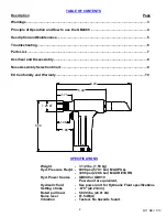
Page 2: ...assembly 8 Nose Assembly Selection Chart 9 EU Conformity and Warranty 10 SPECIFICATIONS Weight 3 1 2 lbs 1 59 kg Hyd Pressure Req d 8400 psi 579 1 bar MAX PULL 3200 psi 220 6 bar MAX RETURN Hyd Power Source GB940 or GB910 Powerunit or equivalent Hydraulic fluid See power unit for Hydraulic Fluid specifications Setting stroke 875 22 23mm Rated pull load 5 600 lbs 24 91 kN Noise level 81 5 dB A Vibr...

Page 3: ...jury may result WARNING It is required to use hearing protection A test was carried out in a simulated work environment where the background level was 73 2 dB A In this condition the max level was 81 5 dB A Therefore it is required where prolonged use hearing protection be used CAUTION Do not use beyond the design intent WARNING Tool must be maintained in a safe working condition at all times and ...

Page 4: ...OR MUST READ AND UNDERSTAND ALL WARNINGS AND CAUTIONS WARNING IT IS REQUIRED THAT EYE PROTECTION AND HEARING PROTECTION BE WORN DURING OPERA TION WARNING DO NOT PULL RIVET IN THE AIR PERSONAL INJURY FROM FASTENER EJECTING MAY OCCUR CAUTION DO NOT USE BEYOND THE DESIGN INTENT 1 Set power supply to the recommended pressure 8 400 psi 579 1 bar for the pull and 3 200 psi 220 6 bar for the return 2 Con...

Page 5: ...INTENANCE WARNING BE SURE POWERUNIT IS DISCONNECTED BEFORE CLEANING OR WHEN REPLACING WORN OR DAMAGED COMPONENTS SEVERE PERSONAL INJURY MAY OCCUR IF POWER SOURCE IS NOT DISCONNECTED The performance of any tool depends upon good maintenance practices Following these minimal require ments for service and care will extend the life of your tool Only use a hydraulic power source equipped with relief va...

Page 6: ...RAULIC OIL OVERHEATS a Powerunit motor rotation reversed Electrical connections reversed See powerunit instructional manual b Restrictions in either hydraulic lines hoses or couplings Check and Tighten clean or replace 5 OIL LEAKAGE a Hydraulic oil leaks from connections Tighten threaded connections Do not use Teflon tape b Oil leaks from tool Determine source of leak and replace worn or defective...

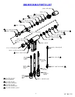
Page 7: ...AL 403806 O RING 248008 FRONT GLAND 206136 ELECTRIC CORD 585044 CONNECTOR MALE 206119 2 HYD HOSE 12 FT 403431 REDUCER 585038 COUPLER FEMALE 240128 STRAIN RELIEF 240128 STRAIN RELIEF 208126 AIR HOSE 208127 MALE DISCONNECT 401731 SET SCREW 401104 BACK UP RING 401110 BACK UP RING 585047 COUPLER MALE 240123 AIR ACTUATOR 240122 ELECTRIC ACTUATOR 1 INCLUDED IN 248010 PISTON ASSEMBLY 1 1 1 2 INCLUDED IN ...

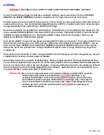
Page 8: ...r 405843 front gland ass y 248006 and polyseal 405818 out the rear of the cylinder taking care not to mar cylinder bore Using a small blunt object remove o rings and back up rings from components Clean parts in mineral spirits or other o ring compatible solvent being sure to clean o ring grooves Inspect components for scoring excessive wear or damage Reassembly sequence is opposite of disassembly ...

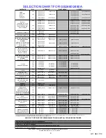
Page 9: ...1B 54RA ASP06 752A 43OS 17 64 ASP08 752B 20 ASP08 752B 45 ASP08 752A 43OS 21 64 ASP10 713 20 ASP10 730 45 ASP10 204D 27OS ASP10 204D 37OS 1 8 MBC04 752C 20 MBC04 752C 45 MBC04 751B 54RA MBC04 752A 43OS 5 32 MBC05 752C 20 MBC05 752C 45 MBC05 751B 54RA MBC05 752A 43OS 3 16 MBC06 752B 20 MBC06 752B 45 MBC06 751B 54RA MBC06 752A 43OS 8 32 GS8 752C 20 GS8 752C 45 GS8 751B 54RA GS8 751A 43OS 10 32 GS10 ...

Page 10: ... the goods covered by this warranty are reworked or subjected to any type of additional processing This warranty is void if Seller is not notified in writing of any rejections or defects within 6 months after the receipt of the material by the customer THIS WARRANTY IS MADE IN LIEU OF ALL OTHER WARRANTIES EXPRESSED OR IMPLIED INCLUDING MERCHANTABILITY WARRANTY DECLARATION OF CONFORMITY WE DECLARE ...

Reviews: