background image


14


REV. 12/22


GB735 INSTALLATION TOOL


OVERHAUL


WARNING

Only qualified and trained personnel shall perform overhaul. 


WARNING

Personnel must read and understand all warnings and cautions. 


WARNING

Tool must be maintained in a safe working condition at all times and examined on a daily basis for damage or 


wear. Any repair must be done by qualified personnel trained on Gage Bilt procedures.


WARNING

Disconnect tool from its power source before performing overhaul. Severe personal injury may occur if power 


source is not disconnected.


WARNING

Excessive contact with hydraulic oil and lubricants should be avoided (See safety data sheet documents for all 


applicable materials).


WARNING

When operating, repairing or overhauling tool, wear approved eye protection. Do not look in front of tool or 


 rear of tool when installing fastener. 


WARNING: 

Ensure air hose is securely connected to avoid possible hose whipping (Air Actuated Tools only).


WARNING: 

Depress actuator assembly

-

air (704130) and disconnect from air, with the piston in the rear position, before overhaul. 


Severe personal injury may occur if air hose is not disconnected. 

USE CAUTION

 when forcing piston rod assembly 


downward with head cylinder removed. Hydraulic oil will eject forcibly from handle assembly.


TOOL DISPOSAL


1.


When tool life is met, drain hydraulic oil from tool and dispose of the hydraulic oil in accordance with the safety datasheet.


2.


Disassemble tool and remove all rubber o

rings, seals, wipers and hydraulic hoses. All tool materials are recyclable except rubber 

o

rings, seals, wipers and hydraulic hoses. Dispose of rubber materials in accordance with the material safety datasheet. 


Note: 


• 

Dispose of hydraulic oil in accordance with manufacture safety datasheet.


• 

All tool materials are recyclable except rubber o

rings, seals and wipers.


• 

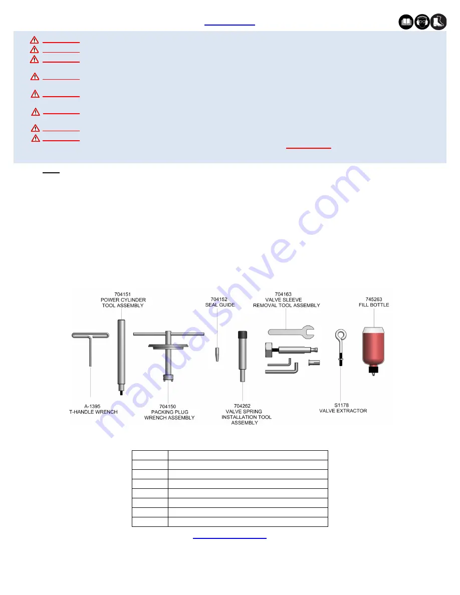
It is recommended that service tool kit (GB735TK) (see below) be used to facilitate overhaul. 


• 

Use of SERVICE KIT (735001), which contains a complete set of o'rings, back

-

up rings, screws, washers and gasket, can 

achieve a complete overhaul.


Perform overhaul in a clean, well lit area using care not to scratch or nick any smooth surface that comes in contact with an o'ring. Use


of Lubriplate® (Gage Bilt part no. 402723) or other lubricant is recommended during reassembly to prevent tearing or distorting of o'rings.


The disassembly and re

-

assembly procedure can be accomplished by utilizing the instructions and parts lists on pgs. 14 

-

 17. Use extreme 

care during disassembly and re

-

assembly not to mar or nick any smooth surface that comes in contact with seals. Before installing seals, 

always apply a good lubricant, such as Lubriplate®, to the surfaces.


Clean parts in mineral spirits or other o'ring compatible solvent being sure to clean o'ring grooves. Inspect components for scoring, 

excessive wear or damage.


Part No.

Description

A-1395

T-Handle Wrench

704151

Power Cylinder Tool Assembly

704150

Packing Plug Wrench Assembly

704152

Seal Guide

704262

Valve Spring Installation Tool Assembly

704163

Valve Sleeve Removal Tool Assembly

S1178

Valve Extractor 

745263

Fill Bottle

GB735TK Service Tool Kit Includes:

Summary of Contents for GB735

Page 1: ...INSTRUCTIONS 44766 Centre Court Clinton Twp MI 48038 USA Ph 1 586 226 1500 Fax 1 586 226 1505 solutions1 gagebilt com www gagebilt com GAGE BILT MADE in USA GAGE BILT TOOLS ARE AVAILABLE WORLDWIDE E M...

Page 2: ...hnical Specifications 4 Description of Functions 5 Safety Warnings 6 Principle of Operation 7 How to Setup the GB735 8 How to use the GB735 9 Maintenance 10 Filling and Bleeding 11 12 Troubleshooting...

Page 3: ...ive from faulty workmanship or material for 1 year from date of shipment Said warranty to remain in effect if and only if such goods are used in accordance with all instructions as to maintenance oper...

Page 4: ...5 28 8 mm fastener setting stroke and a rated pull load of 2 300 lbs 10 2 kN with 90 psi 6 2 bar air pressure at the air inlet The GB735 installation tool operates on 90 to 100 psi 6 2 6 9 bar Max wit...

Page 5: ...5 REV 12 22 GB735 INSTALLATION TOOL DESCRIPTION OF FUNCTIONS Air Inlet Actuator Handle Head Cylinder Deflector Nose Assembly Hanger...

Page 6: ...e to the tool weight it is recommended safety shoes be worn during operation 11 It is recommended tool be operated not more than 50 out of every 60 minutes where prolonged use is expected REPETITIVE M...

Page 7: ...assembly is then directed through the valve sleeve and exhausted out of the bottom of tool Simultaneously the piston rod assembly connected to the air piston assembly is also moving down forcing hydra...

Page 8: ...s WARNING Operator MUST read and understand all warnings and cautions WARNING It is required that eye protection hearing protection and safety boots be worn at all times while handling this equipment...

Page 9: ...re is adequate clearance for tool and operator s hands before proceeding Keep fingers clear of any moving parts Keep fingers clear from fasteners and installed materials Severe personal injury may res...

Page 10: ...and reducing downtime Keep nose assemblies especially jaws clean and free of chips and debris Lube jaws and collet surfaces that jaws ride on with light machine oil on a daily basis All Screwed End Ca...

Page 11: ...e hole for o ring S832 to the top being careful not to get oil into the air passage 3 Place gasket 704129 and o ring S832 on top of the handle assembly 722132 4 Push piston 735107 to rear of head cyli...

Page 12: ...d torque to 35 40 inch lbs 3 95 4 52 Nm Do not over tighten 13 Connect tool to air supply and cycle tool ten times 14 Using a pair of calipers check tool for full stroke 1 135 28 8 mm using instructio...

Page 13: ...71 mm Clear and size or replace 3 NO OPERATION WHEN ACTUATOR LEVER ASSEMBLY 704343 IS DEPRESSED a Tool seized due to mechanical failure or damaged parts 4 OIL LEAKAGE a DO NOT OPERATE WITH OIL LEAKIN...

Page 14: ...als wipers and hydraulic hoses All tool materials are recyclable except rubber o rings seals wipers and hydraulic hoses Dispose of rubber materials in accordance with the material safety datasheet Not...

Page 15: ...assembly 722132 2 Insert a 5 8 open end box wrench adjustable wrench around actuator assembly air 704130 3 Loosen the actuator assembly air 704130 4 Remove wrench Unthread and remove the actuator ass...

Page 16: ...the seal guide 704152 to the piston rod assembly 731333 and tap the piston rod assembly 731333 through the packing plug 704118 3 Attach air piston assembly 704121 and flexlock nut 400559 Torque flexlo...

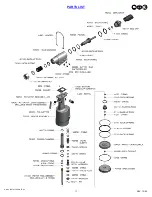
Page 17: ...17 REV 12 22 GB735 INSTALLATION TOOL PARTS LIST...

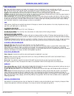
Page 18: ...s material undergoes combustion ACCIDENTAL RELEASE MEASURES Protective Measures Eliminate all sources of ignition in vicinity of spilled material Spill Management Stop the source of the release if you...

Page 19: ...19 REV 12 22 GB735 INSTALLATION TOOL This page intentionally left blank...

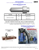
Page 20: ...0 1 4 BOB08 735 20 BOBTAIL LOCKBOLT NOTE THE LAST 2 DIGITS OF THE NOSE ASSEMBLY REPRESENTS THE LENGTH THE NOSE ASSEMBLY EXTENDS FROM THE TOOL I e 41 4 1 inches GAGE BILT CERTIFIES THE GB735 WILL INSTA...

Reviews: