13
Flexible aluminium pipes, corrosion-protected
sheet metal pipes and
exhaust air
pipes whose
material conforms to fire B1 in accordance with
DIN 4102 can be used. Exhaust air pipes should
have a nominal diameter of 150 mm.
Pay particular attention to ensuring
that
– the exhaust air ducts and pipes are kept as short
as possible
– the pipes are not laid at an acute angle, but as
bends and that they are inserted into the shaft at
an inclined upward angle and
– there are no cross-sectional constrictions in the
upward direction (this reduces the volume flow).
As
standard
, the blow-out opening of the wall hood
is in the upward direction.
To pass exhaust air through the outer wall, we
recommend the use of our telescopic wall box
TM 150-045 (Ø 150).
Note:
To prevent the ingress of water, e.g. condensate or
rain water from an uncovered exhaust air shaft, our
condensate separator RV 060-150 must be installed
in the exhaust air line. The condensate separator
must still be acciessible after installation.
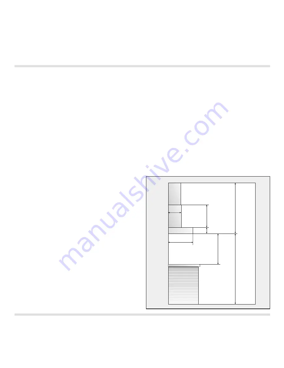
The duct units listed below are available
depending on the height of the ceiling:
Stainless steel-design ventilation duct:
LK 530-010
for ceiling heights of 2.20 - 2.66 m
LK 530-020
for ceiling heights of 2.66 - 3.15 m
Aluminium-design ventilation duct:
LK 530-011
for ceiling heights of 2.20 - 2.66 m
LK 530-021
for ceiling heights of 2.66 - 3.15 m
The dimensions above refer to a distance of 1.60 m
from the floor to the bottom edge of the hood.
If required, custom made duct units are available at
an extra charge.
The socket must be place behind the duct cover on
the wall.
Fig. 18
550
260
100
480
1600
600
-
1550
H
ood
height
min.
600
over
electric
cooker
min.
700
over
gas
cooker
2
.2
0
-
3
.1
5
C
e
iling
height


