background image

Replacing the main nozzle 2
Proceed as follows:

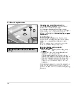
– The main nozzle 2 is visible after detaching the

burner cover (see Fig. 11). It is unscrewed with a
special screw key.  

– Unscrew the nozzle and insert the new nozzle as

specified in the main nozzle table. The nozzle
must be screwed in fully and firmly (torque 
1.5 Nm) (metallic seal). 

– Please do not forget to stick the new adhesive

label included with the nozzle set over the old
adhesive label on the gas connection, thus
documenting the changeover to a different gas
type.

Checking functions

The flames are adjusted correctly if no yellow tips
are visible and if they do not go out when switching
over swiftly from the high to the low setting.

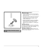
Adjusting the primary air

The primary air setting for different gases is only
defined by the diverse nozzle shapes and therefore
does not require adjustment.

17

Fig. 11

See table on Page 12 for details of nozzle
settings.

Summary of Contents for KG 260 AU

Page 1: ...2 2 Special accessories Page 7 2 3 Operating principle Page 8 3 Operation Page 9 4 Cleaning and care Page 10 5 Maintenance Page 11 5 1 General Page 11 5 2 Remedying slight malfunctions yourself Page 1...

Page 2: ...this appliance Do not spray aerosols in the vicinity of this appliance while it is in operation WHAT TO DO IF YOU SMELL GAS Do not try to light any appliance Do not touch any electrical switch do not...

Page 3: ...connected from the gas supply piping system during any pressure testing of the system at test pressures in excess of 3 5 kPa 1 2 psig The appliance must be isolated from the gas supply piping system b...

Page 4: ...and assembly instructions conscientiously before operating it for the first time The instructions contain important notes on use installation and maintenance of the appliance You will find notes on pa...

Page 5: ...t circuits Isolate the appliance from the mains during every maintenance operation To do this remove the mains plug or isolate the corresponding fuse Close the gas supply Repairs must be carried out b...

Page 6: ...also save gas and reduce pollution Note The appliance must not be combined with hob ventilators VL 040 041 Whenever the gas hob is fitted under a vapour extractor hood always cover the rings with pots...

Page 7: ...ht cooking position 7 Control knob for the front right cooking position 8 Burner head cover 9 Burner head 10 Spark plug for automatic ignition 11 Thermal sensor to safeguard the flame You can order th...

Page 8: ...kW referred to Hs gross calorific value 8 4 kW referred to Hi calorific value The specified rated load is defined by installation of the fixed nozzles The gas hob is converted to a different gas type...

Page 9: ...seconds turn the control knob further to the left to the low position and then back to the high position after ignition It is often faster to ignite in the low position because the various gases have...

Page 10: ...ead with a moist cloth Allow burnt in remainders to soak with a little water and detergent This loosens even the most stubborn of soiling Do not use any abrasive agents and abrasive sponges As the res...

Page 11: ...abnormal operation is indicated In that case call Sampford Staff Pty Ltd 421 Smith Street Fitzroy Vic 3065 Tel 03 9418 5888 Service Centres in other States Melbourne Y 03 9418 5888 Sydney Y 02 9331 88...

Page 12: ...al data gas Technical data electrical Rated consumption 0 8 W Voltage 220 240 V Frequency 50 60 Hz Technical modifications reserved 6 Technical data Settings table Countries AU AU Gas family Natural g...

Page 13: ...e on ventilation To ensure good combustion the room in which this appliance is installed must have a minimum volume of 10 m3 and a door that opens out to outdoors or a window that can be opened Warnin...

Page 14: ...emains accessible after installation of the appliance When making the connection make sure that the lead cannot come into contact with hot parts of the hob Warning This appliance is equipped with a th...

Page 15: ...licable is visible after opening the door of the furniture item By means of the included R 1 2 connection bracket on the appliance end with the affiliated washer the appliance must be connected to a f...

Page 16: ...tting nozzle is screwed in fully at the works and so the lowest quantity is set Replacing the low setting nozzle 1 Proceed as follows Disconnect the appliance from the power supply Remove the cover fr...

Page 17: ...the new adhesive label included with the nozzle set over the old adhesive label on the gas connection thus documenting the changeover to a different gas type Checking functions The flames are adjuste...

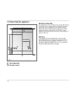
Page 18: ...with the centre marking on the worktop Fig 13 Lower the appliance into the worktop Make sure that the engaging lugs on the appliance lie exactly on the clamping springs Press the appliance firmly int...

Page 19: ...FICE Y 03 9418 5888 GAGGENAU HAUSGER TE GMBH P O BOX 10 02 50 D 80076 M NCHEN Y 0 89 45 90 01 FAX 0 89 45 90 23 47 Service Centres in other States Melbourne Y 03 9418 5888 Sydney Y 02 9331 8888 Adelai...

Page 20: ...Operating and assembly instructions KG 260 AU Built in gas cooktop...

Reviews: