


5
Installation Procedure
en-us
Installation Procedure
Installation Procedure
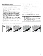
Observe the following when installing:
▯
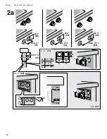
When installing the control knobs in the work surface,
seal the edges of the holes to make sure that they are
water-tight.
▯
Depending on the distance between the control
knobs, it may be necessary to break off the retaining
plate at the perforation.
▯
When installing an individual control knob, use two
screws to hold the retaining plate in place and prevent
it from rotating.
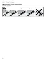
For stone countertops, use temperature-resistant two-
component adhesive (for metal to stone) to adhere the
retaining plate.
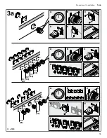
▯
Remove the protective film on the back of the
illuminated ring before installing.
▯
Ensure that the control knobs are allocated to the
correct burners during installation.
▯
The marking at the side to identify the control knobs
must always be on the left.
▯
The two cable connectors on the control knob are
identical.
▯
After installing, check that all plug connections fit
correctly.
▯
After installing all the cables, secure them to the
retaining plate by bending the tab down.
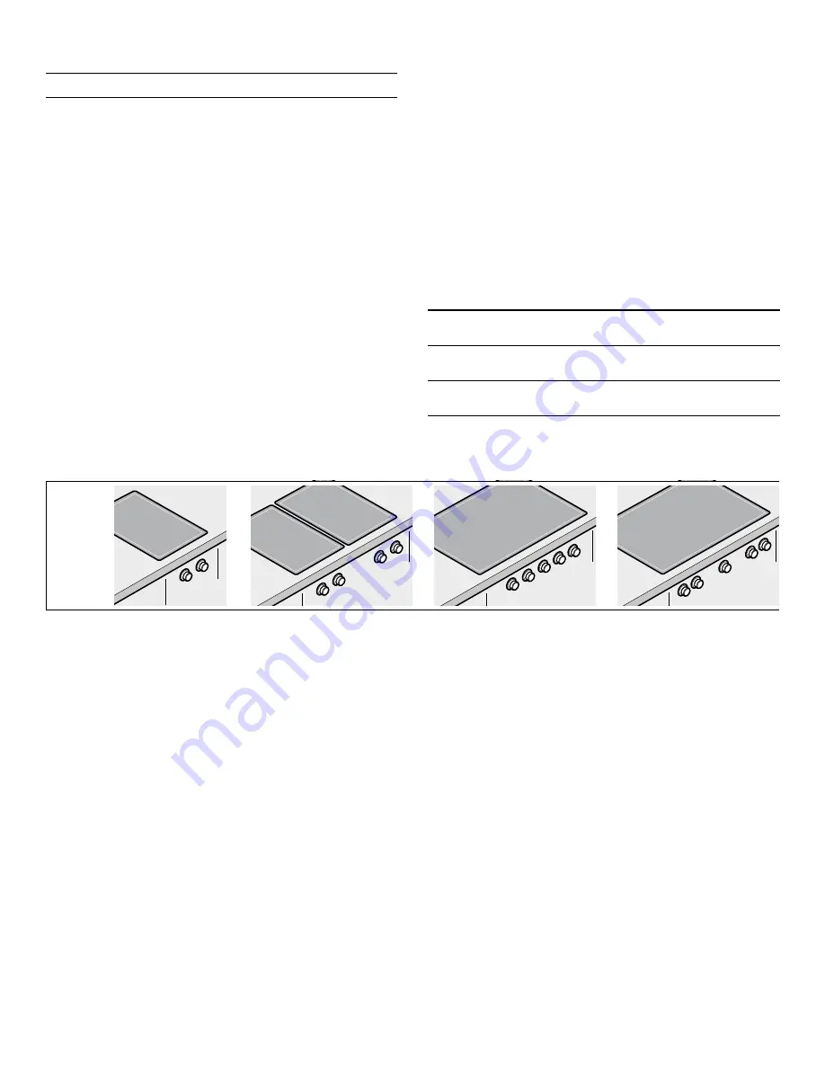
Follow the instructions in the manual for the type of
installation you require:
Installation on the front of the cabinet underneath the appliance
a
"Installation on the front of the cabinet
underneath the appliance" on page 5
b
"Installation in the countertop in front of
c
"Installation in the countertop next to the
D
Summary of Contents for Vario 400 Series
Page 6: ...6 en us Installation Procedure D PLQ RSW PD 5 PP PLQ...
Page 7: ...7 Installation Procedure en us D PP...
Page 8: ...8 en us Installation Procedure Installation in the countertop in front of the appliance E...
Page 9: ...9 Installation Procedure en us E PLQ RSW PD PP 5 PLQ PLQ PP...
Page 10: ...10 en us Installation Procedure E PP...
Page 11: ...11 Installation Procedure en us Installation in the countertop next to the appliance F...
Page 12: ...12 en us Installation Procedure F PLQ RSW PD 0 250 PP PLQ PLQ 5 PP...
Page 13: ...13 Installation Procedure en us F...
Page 18: ...18 fr ca Proc dure d installation D PLQ RSW PD 5 PP PLQ...
Page 19: ...19 Proc dure d installation fr ca D PP...
Page 21: ...21 Proc dure d installation fr ca E PLQ RSW PD PP 5 PLQ PLQ PP...
Page 22: ...22 fr ca Proc dure d installation E PP...
Page 24: ...24 fr ca Proc dure d installation F PLQ RSW PD 0 250 PP PLQ PLQ 5 PP...
Page 25: ...25 Proc dure d installation fr ca F...
Page 30: ...30 es mx Procedimiento de instalaci n D PLQ RSW PD 5 PP PLQ...
Page 31: ...31 Procedimiento de instalaci n es mx D PP...
Page 32: ...32 es mx Procedimiento de instalaci n Colocaci n en cubierta delante del electrodom stico E...
Page 33: ...33 Procedimiento de instalaci n es mx E PLQ RSW PD PP 5 PLQ PLQ PP...
Page 34: ...34 es mx Procedimiento de instalaci n E PP...
Page 35: ...35 Procedimiento de instalaci n es mx Colocaci n en cubierta junto al electrodom stico F...
Page 36: ...36 es mx Procedimiento de instalaci n F PLQ RSW PD 0 250 PP PLQ PLQ 5 PP...
Page 37: ...37 Procedimiento de instalaci n es mx F...
Page 38: ......
Page 39: ......


