Numbers indicated
inside parenthesis ( ) = mm
R
1
/
8
" (R 3)
90°
70" (1.8 m)
A
: When installing with appliance cove, take the deeper cut-out
into consideration(see separate planning notes)
B:
5
1
/
8
" (130 mm) in the area of the cable clamp (left, on the rear side).
min. 4
1
/
8
" (105)
max. 6
3
/
8
" (162)
min. 2"
(50)
dia. 2
1
/
8
"
(60)
dia. 1
3
/
8
" (35)
min. 1
3
/
8
" (35)
19
3
/
8
"
±1
/
16
" (492
±2)
14
15
/
16
"
(380)
20
1
/
2
" (520) (
A
)
1
/
8
" (3)
14
3
/
16
"
±1
/
16
"
(360
±2
)
3
9
/
16
" (90)
4
1
/
2
" (115) (
B
)
5
1
/
2
"
(140)
8
15
/
16
"
(227)
11"
(280)
3" (76)
(
A
)
1
/
8
"
(3.5
-0.5
)
R
1
/
8
" (3)
R
3
/
16
"
(5
+1
)
min. 1
3
/
8
" (35)
min. 4
1
/
4
" (109)
max. 6
1
/
2
" (166)
min. 2"
(50)
dia. 2
1
/
8
"
(60)
dia. 1
3
/
8
" (35)
70" (1.8 m)
90°
14
15
/
16
"
(380)
20
1
/
2
" (520) (
A
)
19
3
/
8
"
±1
/
16
" (492
±2
) (
A
)
20
11
/
16
"
+1
/
16
" (526
+2
) (
A
)
4
5
/
8
" (118) (
B
)
1
/
8
"
(3)
14
3
/
16
"
±1
/
16
"
(360
±2
)
15
3
/
16
"
+1
/
16
"
(386
+2
)
3
9
/
16
"
(90)
5
1
/
2
"
(140)
8
15
/
16
"
(227)
11"
(280)
3" (76)
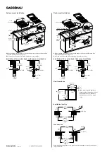
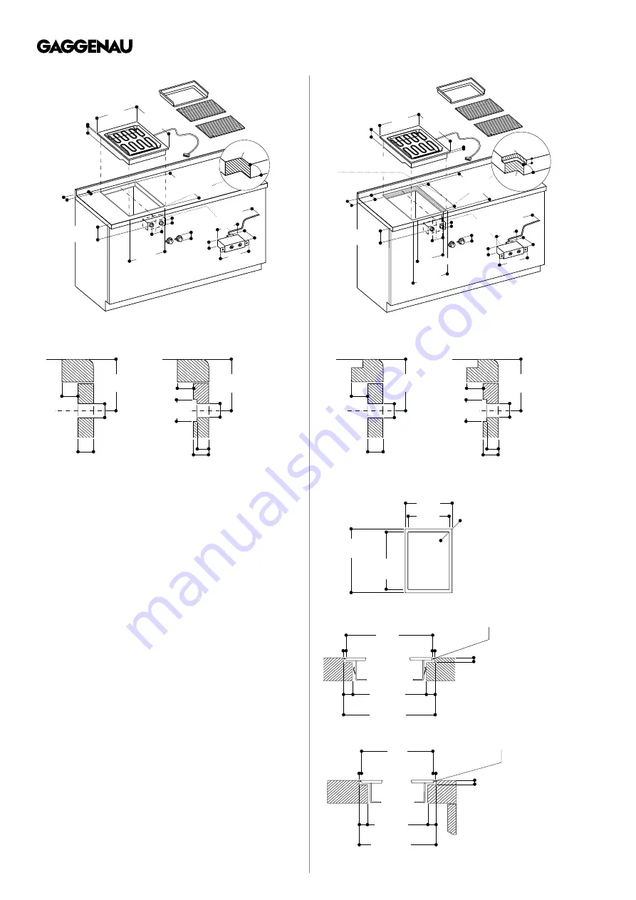
When installing with appliance cover, pay attention to the deeper cut-out and the front and
rear groove width.
Surface-mount Installation
Flush-mount Installation
Control knob installation, surface-mounted installation
ø 1
3
/
8
" (35)
ø 1
3
/
8
" (35)
min.
3
/
16
" (5)
min.
3
/
16
" (5)
4
1
/
8
"-6
3
/
8
"
(105-162)
4
1
/
8
"-6
3
/
8
"
(105-162)
5
/
8
"-1"
(16-26)
D =1" (26)
D
>
1" (26)
3
1
/
8
"x12
3
/
16
"
(80x310)
Installation of the control knob; surface-mount installation
Control knob installation, flush-mounted installation
ø 1
3
/
8
" (35)
ø 1
3
/
8
" (35)
min.
3
/
16
" (5)
min.
3
/
16
" (5)
4
1
/
4
"-6
1
/
2
"
(109-166)
4
1
/
4
"-6
1
/
2
"
(109-166)
5
/
8
"-1"
(16-26)
D =1" (26)
D
>
1" (26)
3
1
/
8
"x12
3
/
16
"
(80x310)
Installation of the control knob; flush-mount installation
fill with
silicone
Longitudinal section
1
/
8
" (3,5
-0,5
)
14
3
/
16
"
±1
/
16
"
(360
±2
)
14
15
/
16
"
(380)
15
3
/
16
"
+1
/
16
"
(386
+2
)
1
/
2
"
(13)
1
/
2
"
(13)
1
/
8
"
(3
+1
)
1
/
8
"
(3
+1
)
Longitudinal section
Cross-section
fill with
silicone
1
/
8
" (3.5
-0.5
)
19
3
/
8
"
±1
/
16
"
(492
±2
)
20
11
/
16
"
+1
/
16
"
(526
+2
)
11
/
16
"
(17)
11
/
16
"
(17)
1
/
8
"
(3
+1
)
1
/
8
"
(3
+1
)
20
1
/
2
"
(520)
When installing with appliance cover or adjustment strip, pay attention to
the deeper cut-out and the front and rear groove width.
Cross-section
A
: When installing with appliance cove, take the deeper cut-out into consideration. See
separate planning notes on page 113.
B
: 5 ⅛" (130 mm) in the area of the cable clamp (left, on the rear side).
A
: When installing with appliance cove, take the deeper cut-out into consideration. See
separate planning notes on page 113.
B
: 5 ⅛" (130 mm) in the area of the cable clamp (left, on the rear side).
* with appliance cover or adjustment bar
(observe front and rear asymmetrical assembly,
see separate notes "assembly with
appliance cover/adjustment bar").
View from above
R
3
/
16
"
(R 5
+1
)
R
1
/
8
"
(R 3)
14
3
/
16
"
±1
/
16
"
(360
±2
)
15
3
/
16
"
+1
/
16
"
(386
+2
)
20
11
/
16
"
+1
/
16
"
(526
+2
)
19
3
/
8
"
±1
/
16
"
(492
±2
)
View from above
A
: When installing with appliance
cover consider the deeper cut-out
See separate notes “assembly
with appliance cover” on page
113).
Revised: 31 March 2020