background image

16

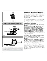
Replacing the low setting nozzles (Fig. 11)

The low setting nozzles for the inner 

(2) 

and outer

(1) 

burners are located in the gas valve. They must

be replaced according to the new gas type and as
specified in the low setting nozzle table. Screw in
the nozzles fully and check that they are tight
(metallic seal).

If it should be necessary to correct the low-setting
nozzles 

(1) 

and 

(2) 

as the result of deviating gas

types and pressure, the flow rate can be increased
by turning to the left.

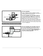
Replacing the main nozzles

Main nozzle replacement for the outer burner
(Fig. 12)

Replace the main nozzle 

(3)

(SW 10) for the high

setting according to the new gas type and as
specified in the nozzle table. Beforehand, loosen
the screw 

(2) 

and push away the air regulation

sleeve 

(1) 

and fix it in place with the screw 

(2)

.

Check the absence of gas leaks on the installed
main nozzle. According to the new gas type, stick
the included adhesive label over the data specified
on the gas connection.

Adjust the air gap according to the table entitled
“Air gap adjustment" for the outer burner.

Main nozzle replacement for the inner burner
(Fig. 13)

Remove the supply line by undoing the union nut

(4) 

(SW 8). Unscrew the injector screw 

(5) 

(SW 12)

and, using a small screwdriver, remove the nozzle

(6) 

from the injector 

(7)

. Install the nozzle

according to the new gas type (see data in the
nozzle table). To do this, fit the nozzle 

(6)

on the

front of the injector screw 

(5)

and screw both of

them into the injector. Plug in the supply line and
screw it in. Check for the absence of leaks. Adjust
the air gap as detailed in the table entitled “Air gap
for inner burner".

Fig. 13

distance in mm

Fig. 12

1

2

3

4

5

6

7

See table on Page 10 for details of nozzle settings.

Fig. 11

2

1

Caution: 

the flame must neither go off nor flash

back when you change over swiftly from the high
to the low setting.

Summary of Contents for VG 231 AU

Page 1: ...Operating and assembly instructions VG 231 Gas cooker...

Page 2: ...peration Page 7 4 Cleaning and care Page 8 5 Maintenance Page 9 5 1 General Page 9 5 2 Remedying slight malfunctions yourself Page 9 6 Technical data Table Page 10 7 Practical tips Page 11 12 7 1 Acce...

Page 3: ...d assembly instructions conscientiously before operating it for the first time The instructions contain important notes on use installation and maintenance of the appliance You will find notes on page...

Page 4: ...every maintenance operation To do this remove the mains plug or actuate the corresponding fuse Close the gas supply Repairs must be carried out by authorised specialists thus ensuring electrical safet...

Page 5: ...setting whenever you remove pots or pans briefly thus saving gas and reducing pollution Whenever the gas hob is fitted under a vapour extractor hood always cover the rings with pots or pans Otherwise...

Page 6: ...se for flame monitor 4 Pot support 5 Control knob for the cooking position 6 Burner cover 7 Burner ring 8 Burner head recess 9 Burner head You can order the following special accessories VV 200 000 co...

Page 7: ...al load amounts to 5 0 kW referred to Hs gross calorific value 4 5 kW referred to Hi calorific value The specified rated load is defined by installation of the fixed nozzles The gas hob is converted t...

Page 8: ...er to the left to the low position and then back to the high position after ignition It is often faster to ignite in the low position because the various gases have a differing ignition response Once...

Page 9: ...water and detergent This loosens even the most stubborn of soiling Do not use any abrasive agents and abrasive sponges As the result of heat development slight dis coloration can appear on the stainl...

Page 10: ...iance will invalidate any warranty claims Only ever use original spare parts 9 5 Maintenance Fault Remedy The burner does not ignite after several attempts Check whether the burner is correctly assemb...

Page 11: ...T BE CH DE BE FR LU NL DE BE CH DK ES AT DE DK ES FI FR FI FR GB GR GB GR IE IS IE IS IT LU IT LU NL PT NL NO PT SE SE Gas family Natural gas Natural gas Natural gas But Prop But Prop Gas type H E G 2...

Page 12: ...cooked as briefly as possible under strong heat and constant stirring In the large round pan everything can be stirred and turned faster and with greater ease than in a conventional frying pan Thanks...

Page 13: ...same time Briefly roast the garlic and ginger and add the meat cubes Reduce the heat Add the Tongku and oyster mushrooms spring onions oyster and fish sauce and the sugar and allow to cook for about...

Page 14: ...connected by a fitter who has been approved by the gas supply company At the same time the guidelines such as DVGW TRGI 86 and TRF 1988 and the regulations of the gas supply companies and of the resp...

Page 15: ...such a way that it cannot come into contact with moving parts of the kitchen element e g drawer Electrical connection Electrical connection AC 220 240 V is established by means of a connecting cable w...

Page 16: ...rner head If the appliance is connected rigidly to a gas main it must be disconnected from the gas network If it is connected via a gas safety hose the appliance only needs to be pushed out of its mou...

Page 17: ...gas leaks on the installed main nozzle According to the new gas type stick the included adhesive label over the data specified on the gas connection Adjust the air gap according to the table entitled...

Page 18: ...e flames burn stably and with low noise Yellow tips must not be visible in the flames The flame must not go off when you switch swiftly from the high to the low setting Firmly screw in the screw 2 aga...

Page 19: ...rking on the worktop Fig 17 Lower the appliance into the worktop Make sure that the engaging lugs on the appliance lie exactly on the clamping springs Press the appliance firmly into the worktop The e...

Reviews: