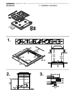


Fitting the appliance
1.
Mark the centre of the recess exactly. Fit the short mounting rail
to the front of the recess and the long mounting rail to the rear
of the recess. Make sure the lugs of the mounting rails lie on
the worktop. The centre marking on the mounting rails must be
precisely flush with the centre marking of the recess.
Note:
when fitting the appliance in a stone worktop glue on the
mounting rails with a temperature-resistant two-component
adhesive (metal on stone).
2.
For combination with the appliance cover VD 201: secure the
appliance cover on the appliance before installation (refer to
the installation manual of VD 201).
3.
Lower the appliance into the cut-out. The snap-in pins on the
appliance must lie exactly on the catch springs. Firmly press
the appliance into the cut-out.
The pins on the appliance must
snap into the catch springs.
Removing the appliance
Disconnect the appliance from the power and the gas supply.
Push out the appliance from below.
Caution!
Risk of damage! Do not lever out the appliance from above.
Gas connection
The supply connection point shall be accessible with the
appliance installed.
Using the R½'' (for appliance side) connection elbow provided,
connect the appliance with the associated gasket to a fixed
connection pipe. For natural gas the regulator must be
connected.
If using a flexible connection
This appliance is approved for connection by a CLASS B hose.
Connection is in compliance with AS/NZS 5601.1
There are two ways to carry out the connection to the main gas
line:
■
A: The hotplate can be connected with rigid pipe.
■
B: Flexible Hose: If installing with a hose assembly, install with
a hose assembly that complies with AS/NZS 1869 (AGA
Approved), 10 mm ID, class Bor D, no more than 1.2 m long
and in accordance with AS/NZS 5601.1. Ensure that the hose
does not contact the hot surfaces of the hotplate, oven,
dishwasher or any other appliance that may be installed
underneath or next to the hotplate. The hose should not be
subjected to abrasion, kinking or permanent deformation and
should be inspected along its entire length with the cooktop in
the installed position. Unions compatible with the hose fittings
must be used and all connections tested for gas leaks.
Before leaving - check all connections for gas leaks with soap
and water. DO NOT use a naked flame for detecting leaks.
Ignite all burners both individually and concurrently to ensure
correct operation of gas valves, burners and ignition. Turn gas
taps to low position and observe stability of the flame for each
burner individually and all together.
Adhere the duplicate data plate to an accessible location near
to the cook top. When satisfied with the cook top, please
instruct the user on the correct method of operation. In case the
appliance fails to operate correctly after all checks have been
carried out, refer to the authorised service provider in your area.
Electrical connection
Check that the appliance has the same voltage and frequency
as the electrical installation system.
The hob is delivered with a mains cable and 3 pin moulded
plug.
Only connect the appliance to sockets which have been fitted
and earthed according to regulations.
The appliance corresponds to type Y: the mains connection
cable must only be replaced by the after-sales service. Check
the cable type and minimum cross section.
Technical data / nozzle table
Total connected load electric 0.8 VA
Nozzle table
Conversion to another type of gas
This gas hob corresponds to the categories specified on the
rating plate. It is possible to convert the appliance to any of the
gases listed on the plate by changing the nozzles. The
modification kit can be ordered via our after-sales service.
Depending on the model the parts required may beincluded in
the scope of delivery.
The conversion must be carried out by an authorised person.
Before carrying out the conversion, turn off the electricity and
gas supply.
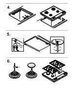
Changing the low burn nozzle – fig. 5:
1.
Remove the cover from the underside of the appliance under
the gas valves. The low burn nozzle is located in the gas valve
and is screwed in from below.
2.
Unscrew the nozzle and insert the new nozzle as specified in
the low-setting nozzle table. The nozzle must be screwed in
fully.
3.
Fit the cover cap again.
Changing the full burn nozzle – fig. 6:
1.
Remove the pan supports and burner lids.
2.
Change the nozzles. Care should be taken to ensure that the
nozzles do not break off when screwed in or out.
3.
Screw the new nozzles in as far as they will go to achieve a
good seal.
4.
Replace the pan supports and burner lids, checking that they
are correctly positioned.
If it should be necessary to correct the low-setting nozzle as the
result of deviating gas types and pressure, the flow rate can be
increased by turning to the left.
These burners do not require the primary air to be adjusted.
Checking functions after the conversion:
The flames are adjusted correctly if no yellow tips are visible
and if they do not go out when switching over swiftly from the
high to the low setting.
Note:
stick the adhesive label included with the nozzle set over
the rating plate of the appliance to document the changeover to
a different gas type.
Gas
Natural Gas
Propane Gas
Pressure
1.0 kPa
2.75 kPa
A-burner full burn
118
74
A-burner low burn
58
36
B-burner full burn
148
87
B-burner low burn
68
42
Total connected load 34.0 MJ (9.4 kW)
31.4 MJ (8.7 kW)
Total consumption
0.9 m³/h
680 g/h
Summary of Contents for VG 232 234 AU
Page 2: ...PD...


