background image

13

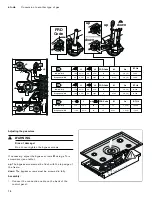
  Conversion to another type of gas   

en-us

Replacing the main nozzles in the standard burner and 
high-output burner:

1.

Remove the pan support and all burner parts.

2.

Undo the fastening screws on the burners and remove 
the control knobs.

3.

Carefully lift up and remove the cooktop and 
disconnect the connection cable on the back of the 
control panel.

4.

Remove the securing clips from the burner pipes. Pull 
out the burner pipes. The electrode can remain 
connected. Unscrew the burners (Torx T20) and pull 
out the burner pipes.

5.

Pull the nozzles off the burner pipes by hand and 
remove the O-ring.

6.

Check that the O-ring is seated correctly in the new 
main nozzles. Fit the nozzles to the burner pipes. Take 
care not to bend the burner pipes when doing so.

7.

Fit the burners onto the burner pipes. Attach the 
securing clips. Screw the burners into place.

8.

Loosen the screw and then adjust the air regulating 
sleeve of the outer burner to the correct setting (see 
nozzle table – L1). Retighten the screw.

9.

Adjust the air regulating sleeve on the inner burner to 
the correct setting by turning or pushing it (see nozzle 
table – L2).

Replacing the main control nozzles for the wok burner:

1.

Remove the securing clips from the burner pipes. Pull 
out the burner pipes. Unscrew the screw on the air 
regulating sleeve. Remove the nozzle retaining head.

2.

Pull off the nozzle and O-ring for the inner burner ring 
by hand. Unscrew the nozzle for the outer burner ring 
(WAF 10).

3.

Check that the O-ring is seated correctly in the new 
main nozzle for the burner inner ring. Fit the nozzle 
onto the burner pipe. Screw the new main nozzle for 
the outer burner ring as far as it will go into the nozzle 
retaining head.

4.

Fit the nozzle retaining head and burner pipes. Fit the 
securing clips.

5.

Loosen the screw and then adjust the air regulating 
sleeve to the correct setting (see nozzle table). 
Retighten the screw.

Summary of Contents for VG 295 250 AU

Page 1: ...DJJHQDX Installation instructions2 Notice de montage16 Instrucciones de instalaci n30 VG 295 250 CA VG 295 150 CA Gas cooktop Table de cuisson gaz Encimera a gas...

Page 2: ...Installation 12 Conversion to another type of gas 12 Customer Service 15 The wiring diagram is available on the last page of this manual Additional information on products accessories replacement part...

Page 3: ...LJKW DQ DSSOLDQFH R QRW WRXFK DQ HOHFWULFDO VZLWFK R QRW XVH DQ SKRQH LQ RXU EXLOGLQJ PPHGLDWHO FDOO RXU JDV VXSSOLHU IURP D QHLJKERU V SKRQH ROORZ WKH JDV VXSSOLHU V LQVWUXFWLRQV I RX FDQQRW UHDFK RX...

Page 4: ...LRQ RI WKLV SSOLDQFH 8QDWWHQGHG DLOXUH WR IROORZ WKLV ZDUQLQJ VWDWHPHQW FRXOG UHVXOW LQ ILUH H SORVLRQ RU EXUQ KD DUG WKDW FRXOG FDXVH SURSHUW GDPDJH SHUVRQDO LQMXU RU GHDWK I D ILUH VKRXOG RFFXU NHHS...

Page 5: ...s with one or more of the following Standards UL 858 The Standard for the Safety of Household Electric Ranges UL 923 The Standard for the Safety of Microwave Cooking Appliances UL 507 The Standard for...

Page 6: ...being turned ON accidentally Installer show the owner the location of the circuit breaker or fuse Mark it for easy reference Gas Safety Install a gas shutoff valve near the appliance It must be easily...

Page 7: ...xible gas connector must not be longer than 36 inches Installer show the owner where the gas shut off valve is located Related Equipment Safety The appliance should only be used if installed by a qual...

Page 8: ...s appliance The hood must be installed according to instructions furnished with the hood 9 CAUTION The appliance should not be installed with a ventilation system that blows air downward toward the bu...

Page 9: ...n installing the gas cooktop shall be The distance from the top of the cooktop to the bottom of cabinets above can be reduced to 26 when the bottom of the wood or metal cabinet is protected by not les...

Page 10: ...Some solid surface countertops require special installations For example heat reflective tape and rounded corners may be necessary Contact the countertop manufacturer for instructions specific to your...

Page 11: ...installation position SERVICER INFO ONLY Connect the gas supply using the U S A elbow and the fiber gasket supplied with the unit The shorter nontapered thread fits into the threaded nut on the cookt...

Page 12: ...ent type of gas by a licensed expert Switch off the power supply and shut off the gas supply before carrying out conversion This gas cooktop conforms to the categories indicated on the rating plate Ch...

Page 13: ...o place 8 Loosen the screw and then adjust the air regulating sleeve of the outer burner to the correct setting see nozzle table L1 Retighten the screw 9 Adjust the air regulating sleeve on the inner...

Page 14: ...ee table up The bypass screws must be flush with the top edge of the frame down The bypass screws must be screwed in fully Assembly 1 Connect the connection cable on the back of the control panel F F...

Page 15: ...vice calls getting your appliance back up and running correctly in the least amount of time possible When you call please indicate the product number E Nr and serial number FD Nr so that we can suppor...

Page 16: ...tion de l installation 26 Changement de type de gaz 26 Service apr s vente 29 Le sch ma de c blage se trouve la derni re page de ce manuel d installation Vous trouverez des informations suppl mentaire...

Page 17: ...FRXUDQW pOHFWULTXH 1H SDV XWLOLVHU GH WpOpSKRQHV GDQV O pGLILFH RPPXQLTXHU LPPpGLDWHPHQW DYHF OH IRXUQLVVHXU GH JD GHSXLV O DSSDUHLO WpOpSKRQLTXH G XQ YRLVLQ 5HVSHFWHU OHV GLUHFWLYHV GX IRXUQLVVHXU G...

Page 18: ...DUHLO VDQV VXUYHLOODQFH H QRQ UHVSHFW GH FHWWH PLVH HQ JDUGH SRXUUDLW HQWUDvQHU XQ LQFHQGLH XQH H SORVLRQ RX XQ ULVTXH GH EU OXUH HW DLQVL FDXVHU GHV GRPPDJHV PDWpULHOV GHV EOHVVXUHV RX OD PRUW 6L O D...

Page 19: ...cien agr La garantie ne couvre pas une mauvaise installation S curit de manutention des appareils Codes et normes de s curit Cet appareil est conforme une ou plusieurs des normes suivantes UL 858 la n...

Page 20: ...l et mis la terre par un technicien qualifi L installation les connexions lectriques et la mise la terre doivent tre conformes tous les codes applicables Avant l installation mettre l appareil hors se...

Page 21: ...e selon le mod le Il doit tre converti pour usage avec l autre type de gaz Un technicien ou un installateur qualifi doit proc der la conversion Il faut convertir l appareil lectrom nager selon les dir...

Page 22: ...u placard V rifiez que la profondeur des armoires situ es au dessus de la table de cuisson ne d passe pas 13 po 330 mm Lors de l installation de la table de cuisson sur un four simple prendre bien soi...

Page 23: ...ards Lors de l installation de la table de cuisson gaz il faut respecter les distances minimales suivantes Le d gagement du haut de la table de cuisson au bas des armoires situ es au dessus peut tre r...

Page 24: ...r r sistance la chaleur Certains plans de travail haute r sistance requi rent des am nagements sp ciaux Par exemple une bande thermor fl chissante et des coins arrondis peuvent tre n cessaires Contact...

Page 25: ...uisson INFORMATION POUR LE SERVICE APRES VENTE Raccorder l alimentation du gaz au moyen du coude U S A et du joint d tanch it en fibre fournis avec l appareil Le filetage court non conique se visse da...

Page 26: ...egazSeul un sp cialiste agr est habilit adapter l appareil un autre type de gaz Avant la conversion coupez l alimentation lectrique et l admission de gaz La plaque de cuisson au gaz correspond aux cat...

Page 27: ...er la douille de l air primaire du br leur ext rieur la dimension correcte apr s avoir desserr la vis voir le tableau des injecteurs L1 Resserrer la vis 9 R gler la douille de l air primaire du br leu...

Page 28: ...p les vis Bypass doivent affleurer avec le bord sup rieur du support grille down les vis Bypass doivent tre enti rement viss es Assemblage 1 Raccorder le c ble de connexion l arri re du panneau de com...

Page 29: ...Serviceapr s venteSi votre appareil doit tre r par notre service apr s vente est votre disposition Nous trouvons toujours une solution adapt e y compris pour viter les visites inutiles de techniciens...

Page 30: ...ctrica 39 Colocaci n de la tapa del quemador 40 Pruebe la instalaci n 40 Cambio a otro tipo de gas 41 Servicio de atenci n al cliente 45 El diagrama de cableado se encuentra en la ltima p gina de este...

Page 31: ...pFWULFR 1R XWLOLFH QLQJ Q WHOpIRQR HQ VX HGLILFLR ODPH LQPHGLDWDPHQWH D VX SURYHHGRU GH JDV GHVGH XQ WHOpIRQR YHFLQR 6LJD ODV LQVWUXFFLRQHV GHO SURYHHGRU GH JDV 6L QR SXHGH FRQWDFWDU D VX SURYHHGRU GH...

Page 32: ...Q GHO DSDUDWR VLQ YLJLODQFLD O LQFXPSOLPLHQWR GH HVWD DGYHUWHQFLD SRGUtD GDU OXJDU D LQFHQGLRV H SORVLRQHV R TXHPDGXUDV TXH SRGUtDQ FDXVDU GDxRV PDWHULDOHV SHUVRQDOHV H LQFOXVR OD PXHUWH 6L VH SURGXFH...

Page 33: ...cubre una instalaci n incorrecta Seguridad de manejo del electrodom stico C digos y normas de seguridad Este aparato cumple con una o varias de las siguientes normas UL 858 la norma de seguridad para...

Page 34: ...os 3 mm en todos los polos Aseg rese de que el electrodom stico sea correctamente instalado y conectado a tierra por un t cnico calificado La instalaci n las conexiones el ctricas y la conexi n a tier...

Page 35: ...ministra con esta unidad El electrodom stico se env a desde la f brica para su uso con gas natural o gas propano seg n el modelo Deber convertirse para su uso con otro tipo de gas Esta adaptaci n tien...

Page 36: ...de la parte inferior del gabinete Verifique que los gabinetes que se encuentran sobre la placa tengan 13 pulg 330 mm de profundidad como m ximo Al instalar una placa sobre un horno individual aseg re...

Page 37: ...spacios m nimos que tienen que mantenerse cuando se instale la parrilla de gas son los siguientes La distancia desde la parte superior de la placa hasta la parte inferior de los gabinetes que se encue...

Page 38: ...abajos de recorte Sellar las superficies de corte termorresistentes Algunas encimeras s lidas requieren condiciones de instalaci n especiales Por ejemplo es posible que se debe utilizar cinta ign fuga...

Page 39: ...er as del agua caliente un radiador o cualquier otro aparato instalado en la vecindad de una parrilla de gas La manguera de seguridad de gas no debe estar expuesta a abrasiones vibraciones dobleces o...

Page 40: ...quemador Control de la colocaci n de la tapa del quemador Realizar un control para asegurarse de que no hay huelgo entre los elementos del quemador Mueva ligeramente los elementos del quemador de lado...

Page 41: ...mbiar la llave del gas completa Para eso ponerse en contacto con el servicio de atenci n al cliente 9 ATENCION Para convertir el regulador a gas LP propano Versi n Maxitrol modelo RV 47 CL PSIG 5 Reti...

Page 42: ...principales del quemador wok 1 Retirar los clips de seguridad de los conductos del quemador Retirar los conductos del quemador Aflojar el tornillo del casquillo de regulaci n del aire Retirar el sopor...

Page 43: ...ci n M con un destornillador Torx ver la tabla up los tornillos de derivaci n deben quedar al ras del borde superior de la base down los tornillos de derivaci n deben enroscarse por completo F F D D D...

Page 44: ...4 Colocar la perilla de control Despu s del cambio comprobar el funcionamiento Las puntas de las llamas no deben ser amarillas Al girar r pidamente la perilla de control entre el m ximo y el m nimo ni...

Page 45: ...ros correspondientes los encontrar en la parte inferior del aparato Para evitar tener que buscar los datos de su aparato cuando los precise es aconsejable anotarlos aqu conjuntamente con el n mero de...

Page 46: ...on circuit diagram VG295 Released 28 29 30 31 REF Components Po th A 1 Control pc board 3 13 A2 User interface module 19 29 B2 Comection socket 4 E1 Spark plug 19 E2 Spark plug 21 B Spark plug 22 E4 S...

Page 47: ......

Page 48: ...DJJHQDX 6 RPH SSOLDQFH RUSRUDWLRQ 0DLQ 6WUHHW 6XLWH UYLQH ZZZ JDJJHQDX FRP XV 6 RPH SSOLDQFHV DJJHQDX DXVJHUlWH PE DUO HU 6WUD H 0 QFKHQ 50 1 9001538658 9001538658 000308 en us es mx fr ca...

Reviews: