background image

13

 Installation Procedure  

en-us

3.

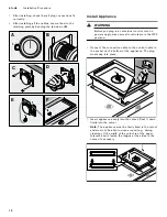
Only for flush mount installation:


Note: 

Make sure that everything is working correctly 

before grouting.

Grout the surrounding gap with a suitable 
temperature-resistant silicone adhesive (e.g., 
OTTOSEAL

®

 S 70). Smooth the joint seal with a 

smoothing agent recommended by the manufacturer. 
Heed the processing instructions for the silicone glue. 
Only start up the appliance after the silicone glue is 
completely dry (at least 24 hours, depending on the 
room temperature).

NOTICE

Unsuitable silicone adhesive causes permanent 
discoloration to natural stone countertops.

4.

Connect the appliance to the mains and check that it 
works correctly. If the appliance is turned off, air may 
be present in the gas line. Turn control knob to 0 and 
reignite. Repeat the process until the appliance 
ignites.

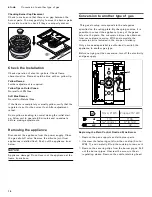
Connect Gas Supply

The appliance is shipped from the factory for use with 
natural gas. It must be converted for use with propane. A 
qualified technician or installer must do the conversion.

Before connecting the appliance, please check whether 
the local connection conditions such as gas type and gas 
pressure match the appliance settings.

Make sure the gas supply is turned off at the manual shut-
off valve before connecting the appliance.

The gas connection must be in a location that permits 
access to the manual shut-off valve and which, if 
applicable, is visible after opening the door of the 
cabinet.

SERVICER INFO ONLY


Connect the gas supply using the ½" U.S.A. elbow and 
the fiber gasket supplied with the unit. The shorter, 
nontapered thread fits into the threaded nut on the hob. 
The longer, tapered U.S.A. thread is for the incoming gas 
supply. Vent the gas line, check for leaks. The gas 
pressure regulator is supplied with the unit and comes 
set for natural gas. To convert regulator to LP (propane) 
gas:

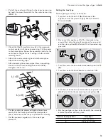
Make-Maxitrol Model RV 47 CL ½ PSIG

1.

Remove the aluminum cap from the top of the 
regulator.

2.

Remove the yellow plastic shaft from the cap by 
pushing it sideways until it pops out of the groove in 
the cap.

3.

Turn the shaft over and push back into the cutout in 
the cap.

4.

Replace the cap on the regulator.

Connect Electrical Supply

Before connecting supply cord to wall receptacle, make 
certain that gas shutoff valve and all burner controls are 
in OFF position.

Electrical connection (AC 110-127 V) is established by 
means of a connecting cord with a grounding contact 
plug connected to a grounded socket, which must also 
be accessible after installation of the gas cooktop.

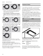
Burner Cap Placement

The burner parts must be properly placed for the cooktop 
to function properly. If the burner parts are not properly 
placed, one or more of the following problems may occur:

Burner flames are too high.

Flames shoot out of burners.

Burners do not ignite.

Burner flames light unevenly.

Burner emits gas odor.

Placing Burner Parts


After electrical connection is complete, assemble the 
burner parts correctly and evenly. When assembling the 
burner parts, make sure that the burner head is placed on 
the base in such a way that the prongs of the burner cap 
fit snugly into the groove of the burner base.

Summary of Contents for VG415211CA

Page 1: ...DJJHQDX Installation instructions 2 Notice de montage 17 Instrucciones de instalaci n 32 VG415211CA Gas wok Wok gaz Wok Gas...

Page 2: ...3 Connect Electrical Supply 13 Burner Cap Placement 13 Check the Installation 14 Removing the appliance 14 Conversion to another type of gas 14 Customer Service 16 Additional information on products a...

Page 3: ...LFDO VZLWFK R QRW XVH DQ SKRQH LQ RXU EXLOGLQJ PPHGLDWHO FDOO RXU JDV VXSSOLHU IURP D QHLJKERU V SKRQH ROORZ WKH JDV VXSSOLHU V LQVWUXFWLRQV I RX FDQQRW UHDFK RXU JDV VXSSOLHU FDOO WKH ILUH GHSDUWPHQW...

Page 4: ...n reaching behind or under appliance Safety Codes and Standards This appliance complies with one or more of the following Standards UL 858 The Standard for the Safety of Household Electric Ranges UL 9...

Page 5: ...power from being turned ON accidentally Installer show the owner the location of the circuit breaker or fuse Mark it for easy reference Gas Safety Install a gas shutoff valve near the appliance It mus...

Page 6: ...ensed by the state province or region where this appliance is being installed Shut off valve must be a T handle gas cock Flexible gas connector must not be longer than 36 inches Installer show the own...

Page 7: ...s appliance The hood must be installed according to instructions furnished with the hood 9 CAUTION The appliance should not be installed with a ventilation system that blows air downward toward the bu...

Page 8: ...0 series for flush installation VA 420 001 Connection strip for combination with other Vario appliances in the 400 series for flush installation with appliance cover compensation strip VA 420 010 Conn...

Page 9: ...The angle between the cut surface and the countertop must be 90 The cut edges at the sides must be flat to ensure a good fit of the retaining springs on the appliance In laminated worktops it may be n...

Page 10: ...sely since the cut out edge is visible on the surface Clean and degrease the cut out edges with a suitable cleaning agent bear in mind silicone manufacturer s processing instructions Combining several...

Page 11: ...the perforation Hold the retaining plate in place against the back of the control panel or the bottom of the countertop or secure it with the enclosed screws 2 When installing a single control knob o...

Page 12: ...y make sure all controls are in the OFF position 1 Connect the connection cable to the control cable in the socket on the bottom of the appliance The plug must snap into place 2 Insert appliance evenl...

Page 13: ...gas supply using the U S A elbow and the fiber gasket supplied with the unit The shorter nontapered thread fits into the threaded nut on the hob The longer tapered U S A thread is for the incoming gas...

Page 14: ...cone joint from appliances installed flush Push out the appliance from below NOTICE Appliance damage Do not lever out the appliance at the frame from above Conversion to another type of gas Conversion...

Page 15: ...Put the burner parts and pan supports in place and ensure that they are positioned correctly 9 Set the pressure regulator to the correct gas pressure Setting the Gas Type Set the gas type via any con...

Page 16: ...r you We work hard to help solve problems quickly and without unnecessary service calls getting your appliance back up and running correctly in the least amount of time possible When you call please i...

Page 17: ...t du gaz 28 Brancher l alimentation lectrique 28 Montage des chapeaux de br leur 28 V rification de l installation 29 D pose de l appareil 29 Changement de type de gaz 29 Service apr s vente 31 Vous t...

Page 18: ...XH 1H SDV XWLOLVHU GH WpOpSKRQHV GDQV O pGLILFH RPPXQLTXHU LPPpGLDWHPHQW DYHF OH IRXUQLVVHXU GH JD GHSXLV O DSSDUHLO WpOpSKRQLTXH G XQ YRLVLQ 5HVSHFWHU OHV GLUHFWLYHV GX IRXUQLVVHXU GH JD 6 LO V DYqUH...

Page 19: ...Une installation non conforme peut entra ner la perte de la garantie S curit de manutention des appareils Certaines surfaces peuvent avoir des bords tranchants Faire attention en tendant le bras derr...

Page 20: ...ectriques et la mise la terre doivent tre conformes tous les codes applicables Avant l installation mettre l appareil hors service au panneau de service Verrouiller le panneau d entr e d lectricit pou...

Page 21: ...l S il doit tre utilis avec du gaz propane il doit tre converti Un technicien ou installateur qualifi devra se charger de la conversion Cet appareil a t certifi comme tant con u pour un fonctionnement...

Page 22: ...ment d au moins 5 po 127 mm la base du placard V rifiez que la profondeur des armoires situ es au dessus de la table de cuisson ne d passe pas 13 po 330 mm Lors de l installation de la table de cuisso...

Page 23: ...420 000 R glette de jonction pour associer d autres appareils Vario de la s rie 400 montage en affleurement VA 420 001 R glette de jonction pour associer d autres appareils Vario de la s rie 400 monta...

Page 24: ...nt au sch ma de pose Le plan de coupe doit faire un angle de 90 avec le plan de travail Les bords de coupe lat raux doivent tre plans afin de garantir la fixation des ressorts de maintien sur l appare...

Page 25: ...oupe doit tre nette et pr cise car le bord de coupe est visible en surface Nettoyer et d graisser les bords de coupe avec un produit de nettoyage ad quat respecter les instructions d application du fa...

Page 26: ...re Maintenez la t le de maintien l arri re du bandeau de commande et sous le dessous du plan de travail ou fixez la avec les vis fournies 2 Lors du montage d un bouton de commande individuel ou lorsqu...

Page 27: ...toutes les commandes sont en position OFF d arr t 1 Enfichez le c ble de raccordement pour le bouton de commande dans l orifice situ sous l appareil Le connecteur doit s encliqueter 2 Installez l app...

Page 28: ...it en fibre fournis avec l appareil Le filetage court non conique se visse dans l crou filet Le filetage conique long type U S A est destin l arriv e du gaz Ventiler la conduite de gaz rechercher les...

Page 29: ...net d arr t du gaz Si les appareils sont pos s en affleurement enlever le joint en silicone Faire sortir l appareil en le poussant par le bas AVIS Risque de d t rioration Ne pas extraire l appareil en...

Page 30: ...les supports de casserole en place veillez les positionner correctement 9 R glez le r gulateur de pression sur la pression de gaz correcte R glage du type de gaz R glez le type de gaz sur l un des bo...

Page 31: ...nouveau type de gaz Service apr s vente Serviceapr s venteSi votre appareil doit tre r par notre service apr s vente est votre disposition Nous trouvons toujours une solution adapt e y compris pour v...

Page 32: ...e control 42 Montaje del aparato 43 Conectar el suministro de gas 43 Conexi n de la alimentaci n el ctrica 44 Colocaci n de la tapa del quemador 44 Pruebe la instalaci n 44 Desarmar el equipo 45 Cambi...

Page 33: ...QLQJ Q WHOpIRQR HQ VX HGLILFLR ODPH LQPHGLDWDPHQWH D VX SURYHHGRU GH JDV GHVGH XQ WHOpIRQR YHFLQR 6LJD ODV LQVWUXFFLRQHV GHO SURYHHGRU GH JDV 6L QR SXHGH FRQWDFWDU D VX SURYHHGRU GH JDV FRPXQtTXHVH FR...

Page 34: ...ar perder el derecho a hacer v lida la garant a del producto Seguridad de manejo del electrodom stico Las superficies ocultas pueden tener bordes filosos Proceda con cuidado al intentar tomar el elect...

Page 35: ...amente instalado y conectado a tierra por un t cnico calificado La instalaci n las conexiones el ctricas y la conexi n a tierra deben cumplir con todos los c digos correspondientes Antes de realizar l...

Page 36: ...f brica para uso con gas natural Debe convertirse para uso con propano Un t cnico o instalador calificados deben realizar la conversi n Este electrodom stico ha sido certificado para un funcionamient...

Page 37: ...del gabinete Verifique que los gabinetes que se encuentran sobre la placa tengan 13 pulg 330 mm de profundidad como m ximo Al instalar una placa sobre un horno individual aseg rese de seguir las inst...

Page 38: ...los uno al lado del otro con superficie corrida VA 420 001 Barra de conexi n para combinar con otros equipos Vario de la serie 400 al instalarlos uno al lado del otro con cubierta de equipo barra de c...

Page 39: ...n la placa de trabajo de acuerdo con los planos de montaje El ngulo de la superficie de corte respecto a la placa de trabajo tiene que ser de 90 Los cantos laterales del corte tienen que ser planos pa...

Page 40: ...cimera deben ser realizados por un servicio especializado de acuerdo con el croquis de montaje El recorte debe ser limpio y preciso puesto que el borde cortado se ve en la superficie Limpie y desengra...

Page 41: ...apa del aparato VA 440 010 est disponible por separado como accesorio especial Respetar el espacio adicional para la tapa del aparato al hacer el hueco Instalaci n enrasada Hueco para la perilla de co...

Page 42: ...egar la placa de sujeci n con pegamento de dos componentes metal sobre piedra resistente al calor 3 Retirar la pel cula protectora de la parte trasera del anillo luminoso A 4 Introducir la perilla de...

Page 43: ...adores recomendados por el fabricante Observar las indicaciones para el uso del pegamento a base de silic n Poner en funcionamiento el aparato solo tras el secado completo del pegamento a base de sili...

Page 44: ...uadamente para que la parrilla funcione correctamente Si no se colocan correctamente las partes del quemador pueden presentarse uno o m s de los siguientes problemas Las flamas del quemador ser n dema...

Page 45: ...solicitar por medio de nuestro servicio de atenci n al cliente En muchos modelos el kit de conversi n forma parte del volumen de suministro La conversi n del aparato para otro tipo de gas nicamente p...

Page 46: ...llo 8 Colocar la placa y atornillar uniformemente Colocar los componentes del quemador y el soporte para ollas en la posici n correcta 9 Ajustar el regulador de presi n a la presi n de gas adecuada Aj...

Page 47: ...perilla de control hacia la derecha hasta la posici n 1 L Girar la perilla de control hacia la izquierda hasta la posici n 0 M Esperar a que el anillo luminoso se apague N El ajuste se guarda El anil...

Page 48: ...su aparato cuando los precise es aconsejable anotarlos aqu conjuntamente con el n mero de tel fono del Servicio de atenci n al cliente Tenga en cuenta que la visita del t cnico del servicio de atenci...

Page 49: ...49...

Page 50: ......

Page 51: ......

Page 52: ...DJJHQDX 6 RPH SSOLDQFH RUSRUDWLRQ 0DLQ 6WUHHW 6XLWH UYLQH 86 ZZZ JDJJHQDX XVD FRP 6 RPH SSOLDQFHV DJJHQDX DXVJHUlWH PE DUO HU 6WUD H 0 QFKHQ 50 1 9001154607 9001154607 970516 en us es mx fr ca...

Reviews: