background image

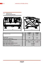
3.2  MAIN COMPONENTS

1.  Main switch

2.  Left steam nozzle

3.  Right steam nozzle

4.  Left steam dispensing lever

5.  Right steam dispensing lever

6.  Filter holder

7.  Water pump pressure gauge

8.  Adjustable support foot

9.  USB ports

10.  Cup warmer tray

11.  Espresso dispensing units

12.  Cup support tray

13.  Mobile stand for short cups

14.  Espresso dispenser zone LED

15.  Casing LED

16.  Hot water dispenser

17.  Hot water dispensing buttons

18.  Touch-screen display

19.  Single/double short espresso dispensing 

button

20.  Single/double long espresso dispensing 

button

21.  Manual espresso dispensing start/stop 

button

ENG

18

GENERAL INFORMATION

Summary of Contents for La Reale

Page 1: ...INSTALLATION AND USE ...

Page 2: ...First Edition Rev 00 REV DESCRIPTION DATE SaGa Coffee S p A Loc Casona 1066 40041 Gaggio Montano BO Italy Tel 39 0534 7741 Fax 39 0534 774808 www evocagroup com ...

Page 3: ...TY 2 1 USE OF THE MACHINE 9 2 1 1 Intended use 9 2 1 2 Improper use 9 2 2 ENVIRONMENTAL CONDITIONS 10 2 3 NOISE 10 2 4 VIBRATIONS 10 2 5 ELECTROMAGNETIC COMPATIBILITY 11 2 6 PROTECTIVE DEVICES 11 2 7 PRESSURISED PARTS 11 2 8 ELECTRICAL SYSTEM AND ISOLATION FROM THE POWER SOURCE 12 2 9 FOOD SAFETY 12 2 10 RESIDUAL RISKS 12 2 11 SAFETY SYMBOLS 14 2 12 REFERENCE STANDARDS 14 DESCRIPTION 3 1 MACHINE F...

Page 4: ...trical connection 28 4 2 4 Commissioning 29 USE 5 1 DESCRIPTION OF THE CONTROLS 31 5 1 1 On Off switch 31 5 1 2 Touch screen display 31 5 1 3 Espresso dispensing unit buttons 33 5 1 4 Hot water dispensing buttons 33 5 1 5 Steam dispensing lever 34 5 2 DAILY ACTIVATION 34 5 2 1 Turning on the machine with machine off 34 5 2 2 Turning on the machine with machine screensaver active 35 5 2 3 Turning o...

Page 5: ... 62 6 2 1 Cleaning the hot water dispenser s aerator filter 62 6 3 ACCESS TO INTERNAL MACHINE COMPONENTS 62 6 3 1 Removing the front cover 62 6 3 2 Removing the right and left side panels 63 6 3 3 Removing the back panel 64 6 3 4 Removing the cup warmer tray 65 6 4 ALARMS 67 6 5 REGULATING THE WATER PUMP FLOW RATE 72 6 6 REGULATING THE PRE INFUSION PRESSURE 72 6 7 RESETTING THE BOILER SAFETY THERM...

Page 6: ...ENG IV CONTENTS ...

Page 7: ...rescriptions reported in the ROHS Directive concerning limitations on the use of the listed hazardous substances are met Valbrembo 11 02 2019 Andrea Zocchi C E O 1 2 SUBJECT AND PURPOSE OF THE MANUAL The subject of this manual is the La Reale professional espresso coffee machine by SaGa Coffee S p A This Manual provides all the instructions and information necessary to properly and safely carry ou...

Page 8: ...ous for the operators and any exposed persons Warning The text refers to warnings concerning operations of particular importance for good machine operation PROHIBITION Indicates the prohibition to perform certain actions and procedures the failure to respect a prohibition could result in damage to the machine even irreparable serious harm to the environment and or dangerous situations for the staf...

Page 9: ...d for whom the information and instructions contained within this Manual are intended are indicated below 1 6 1 Trained operator A professional operator trained for the machine s proper use and aware of the various residual risks present on the machine This individual must receive instructions regarding the locations and functions of all the command and control devices the proper product preparati...

Page 10: ...stomer must promptly notify SaGa Coffee S p A if the EC marking plate is accidentally damaged or detached from the machine or if the manufacturer s seal that secures the plate to the machine is accidentally removed 1 8 LIMITATIONS OF LIABILIT Y SaGa Coffee S p A shall bear no responsibility for any direct or indirect personal injuries or property damage resulting from improper machine use the use ...

Page 11: ...d useful advice for improving the machine s performance and functionality 1 11 GENERAL SAFET Y REQUIREMENTS The machine may only be used by properly trained personnel who have carefully read and fully understood the contents of this Manual and all the safety requirements contained herein The machine may be used by children ages 8 and up and by people with reduced physical sensory or mental capabil...

Page 12: ...d from the power outlet Only use appropriate products to clean the machine and its various parts and avoid any risks of food contamination Only qualified and authorised maintenance personnel may remove the protective devices to perform interventions on the machine s internal parts Do not expose the machine to the elements sun rain etc Prolonged stoppages downtime at temperatures below 0 C zero deg...

Page 13: ...ker compliant with the local legal provisions in order to minimise the risk of electrical shock Never touch the espresso spouts and hot water steam nozzles with your hands or other parts of the body as the liquid steam is dispensed at a high temperatures and could cause serious burns Never operate the machine without water Any obstructions could result in sudden jets of hot liquids or steam with p...

Page 14: ...ENG 8 GENERAL INFORMATION ...

Page 15: ...aracteristics other than those indicated in this manual with one or more parts of its casing removed if not properly installed and connected to its power sources in accordance with the indications contained in this manual the use of the machine s surfaces as tread surfaces or support services for other objects the use of the machine in explosive atmospheres the use of the machine in outdoor enviro...

Page 16: ...very part of the machine itself must not create any hazardous glare and must allow for the characters symbols shown on the screen to be clearly read and for the command and control devices to be easily identified The machine s operating area must have a lighting level of at least 400 lux The user is responsible for evaluating the need for an adequate ventilation system for eliminating the presence...

Page 17: ... parts can only be removed using tools Warning Only qualified maintenance personnel may remove the removable fixed guards and access the machine s internal parts 2 7 PRESSURISED PARTS The pressurised parts that make up the machine s water steam circuit and are subject to Directive 2014 68 EU PED are compliant with the same the declarations of conformity for the utilised components are contained in...

Page 18: ... been designed and built so as to prevent any risk of food contamination The parts that come into contact or could potentially come into contact with food products are made from durable high quality wear resistant non toxic materials All the parts that come into contact or could potentially come into contact with food products can be easily accessed in order to perform cleaning and maintenance int...

Page 19: ... by a qualified and authorised technician risk of burns due to contact with hot internal external surfaces or spraying hot water or steam Caution The maintenance technician is required to wear protective gloves when performing maintenance interventions upon internal parts if the machine has only recently been shut off Risk of being struck by pressurised jets of water or steam when performing maint...

Page 20: ...gn and construction are the following The Machinery Directive 2006 42 EC The Low Voltage Directive 2014 35 EU The Electromagnetic Compatibility Directive EMC 2014 30 EU The Pressure Equipment Directive PED 2014 68 EU EN ISO 12100 2010 Safety of machinery ISO TR 14121 2 2013 Safety of machinery Risk assessment Part 2 Practical guidance and examples of methods UNI EN ISO 14159 2008 Safety of machine...

Page 21: ... 61 251 Measurement methods for electromagnetic fields of household appliances and similar apparatus with regard to human exposure Directive 2011 65 EC RoHS on the restriction of the use of certain hazardous substances in electrical and electronic equipment EEE Directive 2002 96 EC on waste electrical and electronic equipment WEEE Directive 2003 108 EC amending Directive 2002 96 EC on waste electr...

Page 22: ...ENG 16 GENERAL INFORMATION ...

Page 23: ... through the dispensing of hot water or steam It is also equipped with a cup warmer tray Note The description provided in the following sections refers to a machine with two espresso dispensing units The content is also applicable to machines with three espresso dispensing units LA REALE DESCRIPTION 3 ...

Page 24: ...9 USB ports 10 Cup warmer tray 11 Espresso dispensing units 12 Cup support tray 13 Mobile stand for short cups 14 Espresso dispenser zone LED 15 Casing LED 16 Hot water dispenser 17 Hot water dispensing buttons 18 Touch screen display 19 Single double short espresso dispensing button 20 Single double long espresso dispensing button 21 Manual espresso dispensing start stop button ENG 18 GENERAL INF...

Page 25: ...10 A B C 11 7 5 3 D 9 1 8 2 4 6 15 17 A 16 18 19 20 21 B 13 12 D C 14 12 ENG LA REALE GENERAL INFORMATION 19 ...

Page 26: ...presso boiler thermostat unit 1 3 Espresso boiler thermostat unit 2 2 3 1 Note On the machine with 3 espresso dispensing units there is a third thermostat 3 3 2 Components that can be accessed after removing the LH side panel Authorised personnel only 1 Water pump with capacity regulator 2 Master electronic control unit 2 1 ENG 20 GENERAL INFORMATION ...

Page 27: ...be accessed after removing the front cover Authorised personnel only 1 Solenoid valve for steam boiler charging 2 Solenoid valve for 3 way dispensing unit 1 3 Volumetric counter for dispensed water unit 1 4 Solenoid valve for 3 way dispensing unit 2 5 Volumetric counter for dispensed water unit 2 Note On the machine with 3 espresso dispensing units there is a volumetric counter and a solenoid valv...

Page 28: ...erature safety thermostats units 1 and 2 11 Anti vacuum valve 12 Heat exchangers for hot water dispenser 13 Heat exchangers for pre heating the water for the boilers units 1 and 2 14 Tap for boiler disconnection unit 1 15 Tap for boiler disconnection unit 2 Note This paragraph describes a machine with two espresso dispensing units On the machine with 3 units there is Boiler dispensing unit 3 Boile...

Page 29: ...14 3 5 2 10 15 4 6 10 13 11 13 1 8 12 9 7 12 4 A 4 B ENG LA REALE GENERAL INFORMATION 23 ...

Page 30: ...Steam boiler capacity L 11 14 Espresso unit boiler capacity L ea 0 8 Power supply voltage 220 240V 380 415V 3N 50 60 Hz Total power consumed W 8500 10000 Max steam boiler operating pressure 0 14 MPa Max water intake pressure 0 5 MPa Max espresso unit boiler operating pressure 1 2 MPa ENG 24 GENERAL INFORMATION ...

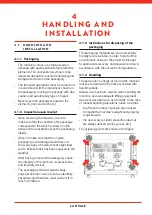
Page 31: ...ved the packaging check the integrity of the machine its accessories and its safety devices The packaging elements plastic bags polystyrene foam nails etc are potentially hazardous and therefore must not be left in reach of children 4 1 3 Instructions for disposing of the packaging The packaging materials are environmentally friendly and recyclable In order to protect the environment however they ...

Page 32: ...d The espresso machine must be placed on a flat stable surface suitable for supporting its weight and must have at least 30cm of free space on all sides Note The uppermost surface of the machine should be at least 1 5m off the ground The ambient temperature must be between 10 and 32 C 50 F and 90 F Do not install the machine outdoors Level the machine using the adjustable support feet and an appro...

Page 33: ...d connect the tray s drain outlet 2 to a drain equipped with a trap for inspection and cleaning 2 1 4 2 2 Water connection Authorised personnel only Warning The water connections must be made in accordance with the current national and local regulations Warning The machine must be supplied with water suitable for human consumption with a hardness level greater than 8 F Note You are advised to inst...

Page 34: ...h the current regulations in the machine s country of use Caution Connect the power cable to the electricity line using a plug in the case of fixed installation a multipolar switch must be installed for network separation with a distance of at least 3mm between the contacts For the voltage change refer to the diagram on the main switch box Caution It is MANDATORY to connect the yellow green wire t...

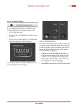
Page 35: ...ppear on the display Menu 1 is displayed next The machine s software checks the water level in the steam boiler and loads water until the level probe is reached Once the level is reached the water loading operation stops and the steam boiler s heating is engaged press the continuous dispensing button on each unit to eliminate any air present in the espresso circuit and fill it completely with wate...

Page 36: ...elector to its ON position Wait for the machine to finish heating before using it Cancel Return to the previous menu Enter Confirm Verify the absence of any leaks from the connections or hoses the proper detection of the water level in the steam boiler that the temperature in the steam boiler corresponds to the set value ENG 30 GENERAL INFORMATION ...

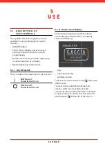
Page 37: ...is located on the lower part of the machine Machine on the switch turns on Machine off the switch turns off 5 1 2 Touch screen display Each espresso dispensing unit has a touch screen display when turned on the display shows the following logo hours and minutes software version To access the user screens touch the centre of the screen The user menu is divided into three main screens which can be u...

Page 38: ...rresponds to the temperature detected in the steam boiler Temperature visualisation begins at 40 C if this value is not reached you will see a series of dashes Button opens the dose programming page Button opens the unit s espresso boiler on off and temperature programming screen Button activates the machine s ECO mode the LED lights on the casing and the espresso units are off the steam boiler is...

Page 39: ...activates the heating function on the steam boiler the espresso unit boilers and the cup warmer 5 1 3 Espresso dispensing unit buttons Single double short espresso dispensing Single double long espresso dispensing Manual espresso dispensing ON OFF 5 1 4 Hot water dispensing buttons Dispenses the amount of hot water set for the relative button in the dose Programming menu Dispenses the amount of ho...

Page 40: ...he same OFF or STAND BY state it was in prior to being shut off Make sure that the machine is receiving water from the water network and that the power line s circuit breaker is engaged Set the main machine switch to l 3 2 the switch turns on the LED lights in the dispensing area turn on as do the ambient LED lights on the sides and back The touch screen displays are activated Water is loaded into...

Page 41: ...f the dispensing buttons the machine is immediately ready for use Visualisation of menu 1 with the machine in ECO mode 5 2 4 Shutting off the machine The machine can be powered off completely or set to stand by mode Complete shut off set the main machine switch to O 3 2 the switch turns off and the machine can only be turned back on by turning the main switch to I again Standby press on the touch ...

Page 42: ...unit Press the indicated button to select either the 1 or 2 cup dispensing mode Press the indicated button to dispense the pre set amount for a short espresso Press the indicated button to dispense the pre set amount for a long espresso Press the indicated button to turn manual espresso dispensing On Off Note The current dispensing operation can be stopped by pressing the same button again ENG 36 ...

Page 43: ...d for a few seconds 5 4 HOT WATER DISPENSING The hot water is dispensed from the relative dispenser 3 2 1 2 After having positioned the appropriate container underneath the dispenser press button 1 or 2 to dispense the desired amount of water Note The current dispensing operation can be stopped by pressing the same button again ENG LA REALE GENERAL INFORMATION 37 ...

Page 44: ...r emulsion level then return the steam control lever to its central position to stop the flow of steam After each use using a clean sponge wash the outside of the steam nozzle with hot water to eliminate any organic residues that may be present clean the inside of the nozzle in the following manner point the pipe towards the cup support tray and using maximum caution perform at least one steam dis...

Page 45: ...TCI Steam boiler temperature Unit temperature offset Sequential heating Cup warmer temperature Purging cycle cold water mix Screensaver Actuator test 1 Actuator test 2 Change password 5 6 1 Technical menu Authorised personnel only Press the indicated button to access the Technical menu Enter the access password Note The default password is 4444 ENG LA REALE GENERAL INFORMATION 39 ...

Page 46: ...an ID number at the top left to make it easier to navigate the menu Number of units For setting the number of coffee units on the machine The possible values are 2 3 Confirm with Pre infusion When the pre infusion parameter is enabled a set time is activated on the coffee doses for an initial infusion stage with a lower pressure 6 6 compared with the real infusion stage that uses the water pump ca...

Page 47: ...takes water from a canister Confirm with Sensitivity Regulates the sensitivity of the probe that detects the water level in the steam boiler The possible values are low medium high Note The sensitivity of the level probe must be regulated on the basis of the hardness of the water water with a scarce mineral content or poor conductivity requires enhanced sensitivity If the sensitivity level is too ...

Page 48: ...he flow rate to the espresso units Confirm with Set the maximum operating time for the steam boiler filling pump after the first switch on Note If the level probe does not detect the filling of the boiler within the time limit the machine stops and a blocking alarm is activated Confirm with Maintenance cycles Sets the number of machine cycles espresso dispensing hot water dispensing When the set n...

Page 49: ...ensing but it does not prevent the machine from being used Note To reset the alarm on the counters page press and hold the relative icon Dose programming Enables or disables the Dose Programming user menu 5 6 2 The possible values are Enabled Disabled Confirm with Enables or disables the possibility to access the menu for setting the espresso boiler temperatures Confirm with ENG LA REALE GENERAL I...

Page 50: ...d the maximum is 20 Confirm with Note When the liquid passes from the espresso boiler to the filter holder outlet it undergoes a temperature drop affected by the ambient temperature Sequential heating When this parameter is enabled the maximum input current limit below 32 Ampere is managed at the supply voltages indicated on the data plate Confirm with Cup warmer temperature 1 2 3 Sets the tempera...

Page 51: ...ature of the water from the hot water dispenser this is done by mixing via a proportional solenoid valve cold water with the hot water from the steam boiler heat exchanger The values that can be set vary from 0 hot to 100 cold Confirm with Screensaver Used to set how many minutes of machine inactivity must elapse before the screensaver is enabled Confirm with ENG LA REALE GENERAL INFORMATION 45 ...

Page 52: ...or unit 2 dispensing T2 solenoid valve for unit 2 pre infusion T3 solenoid valve for steam boiler filling Actuator test 2 By pressing the dispensing buttons you can make sure the actuators in the machine are working properly Confirm with Actuator test 2 Activation Unit 1 T1 espresso heating unit 1 T2 solenoid valve for hot water for tea T3 solenoid valve for cold water mix for tea Unit 2 T1 espres...

Page 53: ...ge password Used to change the new access password with Technical level Enter the new password using the and buttons Confirm with Change password Used to change the new access password with Barista Pro level Enter the new password using the and buttons Confirm with ENG LA REALE GENERAL INFORMATION 47 ...

Page 54: ...Press the indicated button to access the dose programming page 1 2 Press button 1 or 2 to set the hot water dispensing time The hot water programming page will appear Indication of the dose you are programming hot water dispensing Reduces the dispensing time sec Increases the dispensing time sec Cancel Return to the previous menu Enter Confirm ENG 48 GENERAL INFORMATION ...

Page 55: ...ogramming page will appear Indication of the button you are programming purge water dispensing Reduces the quantity of liquid dispensed ml the min value is 3ml Increases the quantity of liquid dispensed ml the max value is 40ml Undo Enter Return to the previous menu Note Programming settings made on unit 1 the first on the left are also applied to unit 2 and unit 3 if installed programming setting...

Page 56: ... Programming of single espresso dispensing A 1 2 3 Press button 1 to program short espresso dispensing B The espresso dose programming page will appear Indication of the button you are programming single short espresso dispensing Indication of the button you are programming double short espresso dispensing By pressing the TEST button you can dispense the programmed dose to test it Reduces the quan...

Page 57: ... to program continuous espresso dispensing Self learning Espresso dispensing can be programmed with self learning 1 2 With the Espresso dose programming page open press button 1 or 2 to begin dispensing and press it again when the required quantity has been dispensed The quantity shown is the quantity programmed in self learning Confirm with ENG LA REALE GENERAL INFORMATION 51 ...

Page 58: ... the doses dispensed by the unit you are working on Single long espresso dispensing counter Double long espresso dispensing counter Single short espresso dispensing counter Double short espresso dispensing counter Continuous espresso dispensing counter Open the next page Washing counter With the first touch of the word reset it turns yellow Press again to confirm the reset ENG 52 GENERAL INFORMATI...

Page 59: ...ows the general machine counters Machine cycle counter when the number of espresso and hot water cycles set in the Technical menu is reached 5 6 1 an alarm is displayed 6 4 Counter for litres through water softener filter when the number of litres set in the Technical menu is reached 5 6 1 an alarm is displayed 6 4 Total number of espresso dispensing operations made by the machine This counter is ...

Page 60: ...ou set the hours minutes and day of the week set automatic switch on switch off defining the on off times and the weekly day of closure 1 switch on and 1 switch off can be set valid for every day of the week except any possible closure days up to 3 when the machine can only be switched on manually ENG 54 GENERAL INFORMATION ...

Page 61: ...tomatic switch on switch off function set as the Auto On time in this case the Auto Off page will not be displayed Warning If the Auto On Auto Off function is used the machine must not be switched off via the main switch but with the button The machine will be switched off but will remain powered the machine power indicator light is still illuminated ENG LA REALE GENERAL INFORMATION 55 ...

Page 62: ...his procedure regulates the temperature of the espresso boiler of the unit you are working on Note The set temperature is the temperature of the water on the espresso panel The temperature of the water in the boiler is higher equal to the offset value set in the Technical menu 5 6 1 Press the indicated button to access the on off and temperature adjustment page for the espresso boiler of the unit ...

Page 63: ...ating OFF the temperature of the water will depend solely on the pre heating carried out by the steam boiler heat exchanger 5 6 6 Cup warmer Press the indicated button to activate deactivate the cup warmer The sequence with every pressing of the button is OFF ON1 ON2 ON3 OFF The temperatures of levels 1 2 and 3 are set in the Technical menu 5 6 1 5 6 7 Lighting Press the indicated button to access...

Page 64: ...e sides of the casing and the back Cancel Return to the previous menu Dispensing area lights and ambient lights OFF Dispensing area lights ON and ambient lights OFF Dispensing area lights OFF and ambient lights ON Dispensing area lights and ambient lights ON ENG 58 GENERAL INFORMATION ...

Page 65: ...the detergent Insert the filter holder in the unit to be washed Press the indicated button to start the wash cycle The machine performs a series of purging operations activating the espresso solenoid valve in sequence The wash water is discharged into the tray through the espresso unit s solenoid valve Note While one unit is being watched the other units can be used normally LA REALE CLEANING AND ...

Page 66: ...ition 6 1 3 Cleaning the perforated disk Use a suitable tool to lever out the perforated disk taking care not to damage the unit gasket Note Wash cycles can be run simultaneously on different units Note A wash cycle cannot be interrupted once it has been initiated 6 1 2 Cleaning the filter holder Note The procedure must be performed with all the filter holders Fill a container of a suitable size w...

Page 67: ...ack into the espresso unit 6 1 4 Cleaning the steam nozzle Unscrew the steam nozzle Pass a pipe cleaner through all the nozzle s holes to eliminate any residues Screw the nozzle back onto the steam pipe 6 1 5 Cleaning the casing Clean the glass on the front using a soft cloth Clean the touch screen displays with a soft cloth dipped in a non alcohol based detergent Use a damp sponge to clean the st...

Page 68: ...supply and that the upstream circuit breaker is ON 6 3 1 Removing the front cover Remove the cup support grille from the tray Loosen the two front slotted head screws Remove the front cover 6 2 WEEKLY MAINTENANCE Expert operator only 6 2 1 Cleaning the hot water dispenser s aerator filter Unscrew the aerator filter from the hot water dispenser Clean the filter Screw the aerator filter back onto th...

Page 69: ...anel Loosen the front and rear slotted head screws Loosen the front slotted head screw Loosen the two screws underneath the tray Loosen the two lower countersunk hex head screws Remove the side panel and disconnect the LED supply connector Repeat the procedure for the LH panel ENG LA REALE GENERAL INFORMATION 63 ...

Page 70: ...l held in place by two magnets Removing the upper cover Loosen the four slotted head screws two on the right and two on the left of the machine Slide the upper cover out to remove it Removing the back panel Loosen the two screws that fix the upper edge of the panel ENG 64 GENERAL INFORMATION ...

Page 71: ...4 Removing the cup warmer tray Remove the RH and LH side panels par 6 3 2 Loosen the two rear screws that fix the cup warmer tray and the two screws that fix the cup warmer plate After removing the RH panel disconnect A the cup warmer temperature probe wiring B the cup warmer supply wiring C the cup warmer earth wiring ENG LA REALE GENERAL INFORMATION 65 ...

Page 72: ...up warmer tray To remove the cup warmer plate from the tray remove the six fixing screws then lift the plate pay attention to the temperature probe supply and earth wiring of the cup warmer ENG 66 GENERAL INFORMATION ...

Page 73: ...lter litre counter reaches the value set in the Technical menu the alarm symbol appears in the relative icon Regenerate the water softener filter To eliminate the alarm press and hold the relative icon the warning triangle will disappear and the filter litre counter will be reset at the value set in the Technical menu During dispensing if the maintenance cycle counter reaches the value set in the ...

Page 74: ...s not read the impulses correctly a specific alarm symbol appears at the bottom right Check the connection wiring between the volumetric counter and the machine board Potential volumetric counter fault check and replace Potential machine board fault check and replace When the steam boiler temperature probe is disconnected circuit open alarm AL3 appears on every unit Check the connection wiring bet...

Page 75: ...he connection wiring between the steam boiler temperature probe and the machine board Potential steam boiler temperature probe fault short circuit check and replace Potential machine board fault check and replace When the espresso boiler temperature probe of an espresso unit reaches a value higher than 140 C alarm AL2 appears on the corresponding unit Check the connection wiring between the espres...

Page 76: ...ge valve fault check and replace Potential machine board fault check and replace When the board clock has synchronisation or battery problems the following alarm appears on the clock programming button on the third page Make a factory pre set in the Technical menu contact an authorised Gaggia Milano Aftersales Service for the relative password The clock board battery may be dead check and replace ...

Page 77: ... 1 when the heating of the steam boiler is not completed within the time limit set in the software alarm AL5 appears on every unit Potential steam boiler heating element fault check and replace Potential steam boiler safety thermostat fault check and replace Potential wiring fault on steam boiler heating element check and replace Potential solid state relay fault check and replace Potential machin...

Page 78: ...moving the LH side panel 6 3 2 Loosen the locking nut 1 Regulate the flow rate by adjusting the screw 2 When you have finished replace the LH side panel 2 1 6 6 REGUL ATING THE PRE INFUSION PRESSURE Remove the protective covers and tighten or loosen the screws of the pressure regulators to increase or reduce the pressure of each espresso dispensing unit during the pre infusion phase ENG 72 GENERAL...

Page 79: ...y thermostats by removing the RH side panel 6 3 2 Identify the thermostat that was triggered 3 3 1 and reset it by pressing the button 1 6 8 MASTER CONTROL UNIT BUFFER BATTERY The master electronic control unit 3 3 2 is fitted with a clock buffer battery of the CR2032u type 3V This battery has a lifespan of approx 10 years ENG LA REALE GENERAL INFORMATION 73 ...

Page 80: ...ENG 74 GENERAL INFORMATION ...

Page 81: ... working life When deciding to dispose of this machine at the end of its working life the user must contact the manufacturer and follow the procedure indicated for the separate disposal of the various parts The proper sorting of the various parts for subsequent recycling treatment and environmentally friendly disposal helps to prevent harm to the environment and human health and facilitates the re...

Page 82: ...ENG 76 GENERAL INFORMATION ...

Page 83: ...LA REALE ELECTRIC AND HYDRAULIC DIAGRAMS 8 ...

Page 84: ...PRE3 EVPRE2 EVPRE1 10 CN48 F 11 CN48 F 9 CN48 8 CN48 7 CN48 5 CN48 4 CN48 3 CN48 2 CN48 1 CN48 6 CN48 NC 2 1 1 3 3 5 5 8 8 1 1 3 0 6 3 15A 250V R 1A 250V F 1A 250V F 1A 250V F 1A 250V F 1A 250V F 1A 250V F 1A 250V F 1A 250V F XPVIEWER35 GRUPPO 1 1 2 3 4 ON OFF 1 2 3 4 3 TASTI SW1 1 2 3 4 ON 1 CN40 12Vdc 1 CN9 5Vdc 2 CN9 GND 2 CN40 RS485 3 CN40 RS485 4 CN40 GND 4 CN41 GND RS232 TTL1 4 CN40 GND RS23...

Page 85: ...W1 1 2 3 4 ON CN5 CN6 CN7 CN8 SW1 1 2 3 4 ON CN5 CN6 CN7 CN8 SW1 1 2 3 4 ON ON OFF 1 2 3 4 ON OFF 1 2 3 4 ON OFF 1 2 3 4 ON OFF 1 2 3 4 USB ON BOARD PROGRAMMING CPU BUS CONNECTION TCI _ TEMPERATURE CONTROL INDIPENDENT TCI DFC _ TEMPERATURE CONTROL INDIPENDENT DYNAMIC FLOW CONTROL CN1 CN2 CN9 CN12 CN48 CN3 P2 CN45 MOD2 MOD3 CN30 CN31 CN36 CN39 CN4 CN5 CN6 CN47 6 3A T 250V CN19 CN21 LA REALE DIAGRAM...

Page 86: ...ENG 7 PURPLE 7 PURPLE 6 6 6 0 0 0 0 0 0 0 0 0 80 DIAGRAMS ...

Page 87: ...ico caldaia Boiler exhaust 1 12 Sonda livello Level feeler 1 11 Valv antidepressione Antivacuum valve 1 10 Valv sicurezza 3 8 1 8bar Security valve 3 8 1 8bar 1 9 Caldaia Boliler 1 8 EV 3 vie EV 3 ways 2 7 Cont volumetrico Flow meter 2 6 Reg pressione Pressure regulator 2 5 Valv espansione Expansion valve 1 4 Valv non ritorno No Return valve 1 3 Manometro pompa Manometer pump 1 2 Multvalvola valv ...

Page 88: ...T 0 1 1 3 E N 0 0 _ 0 7 2 0 1 9 SaGa Coffee S p A Registered Offices Località Casona 1066 40041 Gaggio Montano BO Italy Website www evocagroup com info gaggiaprofessional com ...

Reviews: