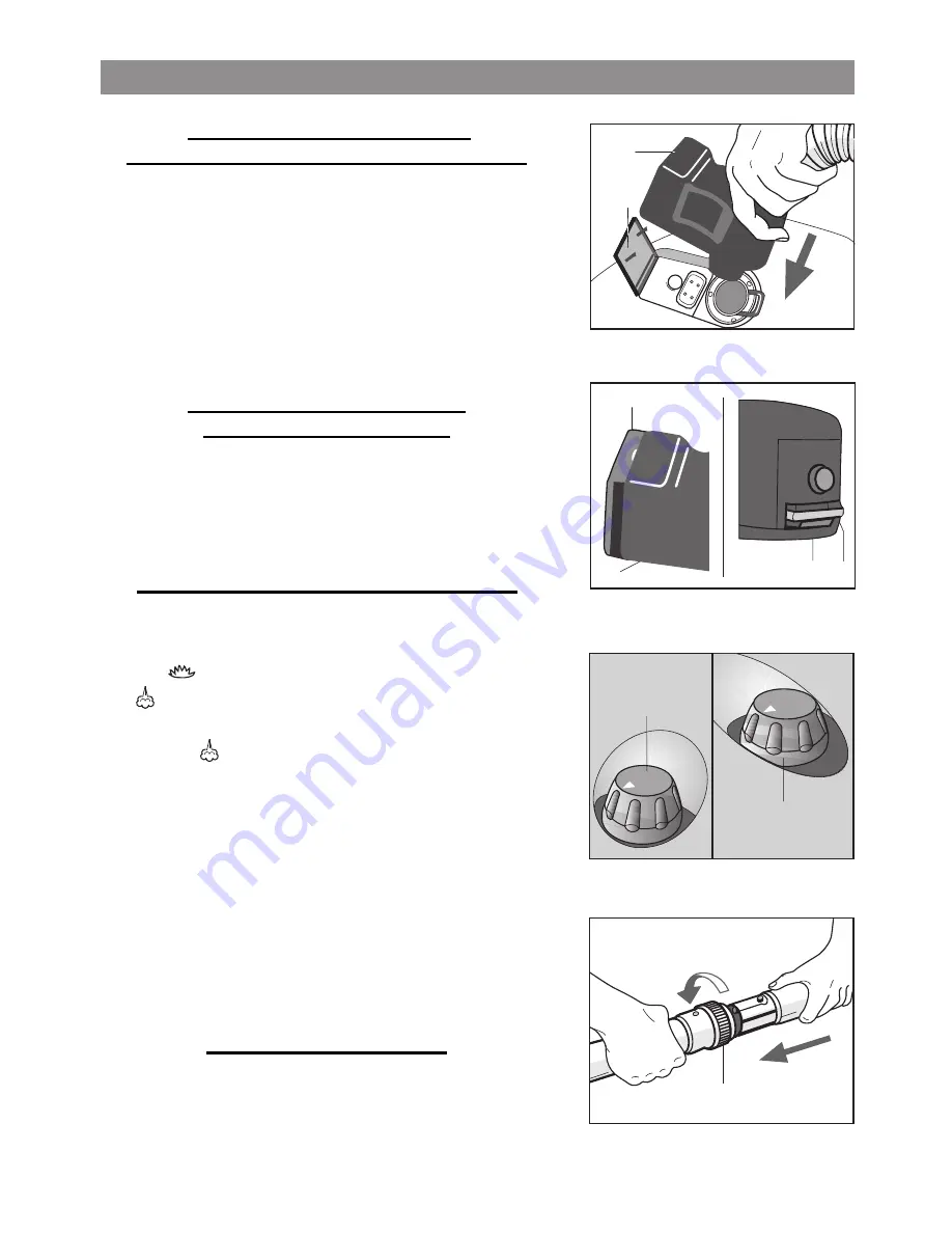
Fig. 10
A
H
Fig. 8
Fig. 9
3
2
5
4
2
3
Fig. 11
6
28
CONNECTING THE HOSE FOR
THE STEAM/VACUUM FUNCTION (Fig. 8-9)
-
Open the flap (2) of the accessories socket (D) and plug
the quick connection (3) of the hose (or of the iron) into the
socket located on the front portion of the appliance. Push it
in as far as it will go.
(Fig.8)
.
-
Close the flap (2) so that it bears against the side of the
quick connection (3) and ensure that the two elements (4-5)
hook up
(Fig. 9)
. This socket provides for steam delivery
and/or suction.
CONNECTING THE HOSE FOR
THE BLOWING FUNCTION
-
You can also fit the quick connection (3) as described
above – for Figures 8 and 9 – into the rear blow socket (O)
but first you have to remove the muffler (P). No steam can
be delivered through this socket.
OPERATING THE APPLIANCE
-
Introduce the plug into the electricity socket.
-
Press warning light buttons (B – Boiler), marked with the
symbol
and (M- Accessories), marked with the sym-
bol
for the steam + suction function.
-
For suction alone, press switch (M- Accessories) marked
with symbol
.
-
Allow the boiler to reach the operating temperature. When
the green warning light (L) is on, the appliance will be ready
for use.
-
To adjust the volume of steam, rotate the knob (H)
(Fig. 10)
. Rotate the knob clockwise for a powerful steam
flow or anti-clockwise for a weaker steam flow.
-
To regulate suction, turn the knob (A). Turn clockwise for
powerful suction and anti-clockwise for reduced suction
(Fig. 10)
.
USING THE ACCESSORIES
To connect the tubes (U) with the accessories, just insert the
male end of one into the female portion of the other and turn
the locking ring nut (6) in the direction shown
(Fig 11)
.
e n g l i s h
Summary of Contents for W1IXX014MENXXC
Page 1: ......
Page 2: ......
Page 4: ...R V S T Z1 U Y Z2 Z3 Z4 G H I L M N A B C D E F O F P Q 2...
Page 24: ...R V S T Z1 U Y Z2 Z3 Z4 G H I L M N A B C D E F O F P Q 22...


