28
INST
INST
INST
INST
INSTALLA
ALLA
ALLA
ALLA
ALLATION 4
TION 4
TION 4
TION 4
TION 4
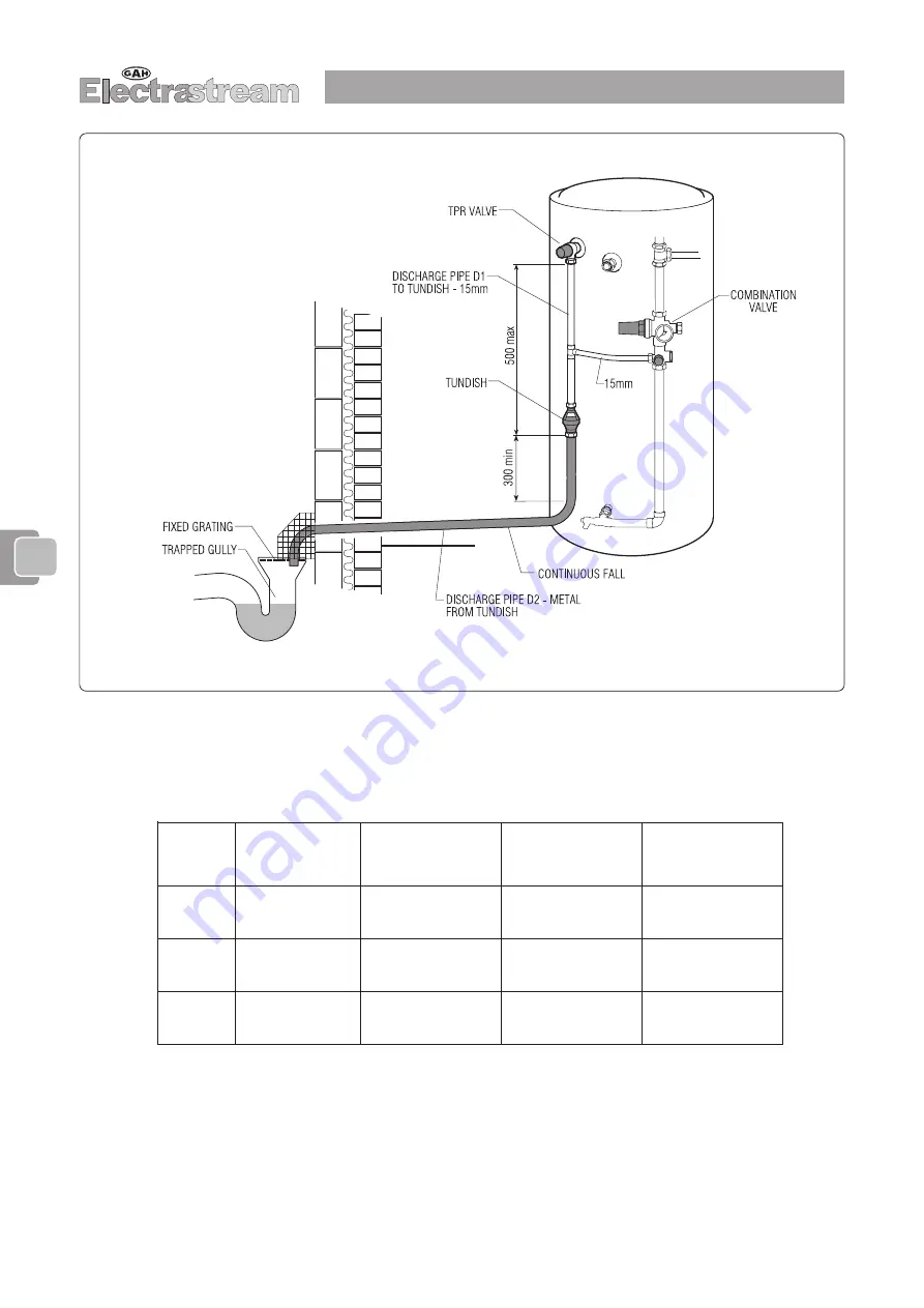
Fig. 4-5b Typical Expansion Discharge Arrangement
4-5.4 Hydraulic Resistance of Discharge Pipework - Table 1
e
zi
s
t
e
lt
u
o
e
v
l
a
V
e
g
r
a
h
c
s
i
d
f
o
e
zi
s
m
u
m
i
n
i
M
(
h
s
i
d
n
u
T
o
t
1
D1
D1
D1
D1
D )
e
p
i
p
e
g
r
a
h
c
s
i
d
f
o
e
zi
s
m
u
m
i
n
i
M
(
h
s
i
d
n
u
T
m
o
rf
2
D2
D2
D2
D2
D )
d
e
w
o
ll
a
e
c
n
a
t
s
is
e
r
m
u
m
ix
a
M
t
h
g
ia
rt
s
f
o
h
t
g
n
e
l
a
s
a
d
e
s
s
e
r
p
x
e
s
d
n
e
b
r
o
s
w
o
b
l
e
o
n
.
e
.i
,
e
p
i
p
h
c
a
e
y
b
d
e
t
a
e
r
c
e
c
n
a
t
s
is
e
R
d
n
e
b
r
o
w
o
b
l
e
½
G
m
m
5
1
m
m
2
2
m
m
8
2
m
m
5
3
m
9
o
t
p
u
m
8
1
o
t
p
u
m
7
2
o
t
p
u
m
8
.
0
m
0
.
1
m
4
.
1
¾
G
m
m
2
2
m
m
8
2
m
m
5
3
m
m
2
4
m
9
o
t
p
u
m
8
1
o
t
p
u
m
7
2
o
t
p
u
m
0
.
1
m
4
.
1
m
7
.
1
1
G
m
m
8
2
m
m
5
3
m
m
2
4
m
m
4
5
m
9
o
t
p
u
m
8
1
o
t
p
u
m
7
2
o
t
p
u
m
4
.
1
m
7
.
1
m
3
.
2
4-5.5 Worked Example
G ½ temperature and pressure relief valve (TPRV) with a discharge pipe (D2) having four
elbows and length of 7m from the tundish to the point of discharge.
From Table 1:-
Maximum resistance allowed for a straight length of 22mm copper discharge pipe (D2)
from G ½ temperature and pressure valve is 9m. Subtract the resistance for four 22mm
elbows at 0.8m each = 3.2m. Therefore the maximum permitted length equates to 5.8m
- as 5.8m is less than the actual length of 7m therefore pipe D2 must be 28mm.
The equivalent hydraulic resistance of discharge pipework needs to be calculated where
the length of D2
D2
D2
D2
D2 exceeds 9m (maximum for one step up in pipe size) including
resistance of elbows or bends. The following table can be used:
44444
Summary of Contents for Electrastream
Page 40: ...39 Notes ...


