


3
CONTENTS
CONTENTS
CONTENTS
CONTENTS
CONTENTS
1 INTRODUCTION
1 INTRODUCTION
1 INTRODUCTION
1 INTRODUCTION
1 INTRODUCTION
2 OPERA
2 OPERA
2 OPERA
2 OPERA
2 OPERATOR CONTROLS
TOR CONTROLS
TOR CONTROLS
TOR CONTROLS
TOR CONTROLS
3 TECHNICAL INFORMA
3 TECHNICAL INFORMA
3 TECHNICAL INFORMA
3 TECHNICAL INFORMA
3 TECHNICAL INFORMATION
TION
TION
TION
TION
5 COMMISSIONING
5 COMMISSIONING
5 COMMISSIONING
5 COMMISSIONING
5 COMMISSIONING
7 F
7 F
7 F
7 F
7 FAUL
AUL
AUL
AUL
AULT FINDING
T FINDING
T FINDING
T FINDING
T FINDING
CONTENTS
CONTENTS
CONTENTS
CONTENTS
CONTENTS
Impor
Impor
Impor
Impor
Important Information
tant Information
tant Information
tant Information
tant Information -----------------------------------------
-----------------------------------------
-----------------------------------------
-----------------------------------------
----------------------------------------- 4
Section 1 Intr
Section 1 Intr
Section 1 Intr
Section 1 Intr
Section 1 Introduction
oduction
oduction
oduction
oduction
1-1 Introduction ---------------------------------------------- 5
1-2 System Layout ------------------------------------------- 8
1-3 Parts Supplied------------------------------------------- 11
1-4 The Electrastream System ------------------------------- 12
1-5 Tri Core Heater Operation -------------------------------- 13
Section 2 Operator Contr
Section 2 Operator Contr
Section 2 Operator Contr
Section 2 Operator Contr
Section 2 Operator Controls
ols
ols
ols
ols
2-1 System Control ------------------------------------------ 14
2-2 Electrastream Control Unit ------------------------------- 16
2-3 Shut Off Valves ------------------------------------------ 20
2-4 Temperature & Pressure Relief Discharge ---------------- 22
2-5 Thermostatic Mixing Valve ------------------------------ 22
2-6 Servicing ------------------------------------------------ 22
Section 3 T
Section 3 T
Section 3 T
Section 3 T
Section 3 Technical Information
echnical Information
echnical Information
echnical Information
echnical Information
3-1 Specifications ------------------------------------------- 23
3-2 Dimensions --------------------------------------------- 25
3-3 Wiring --------------------------------------------------- 29
Section 4 Installation
Section 4 Installation
Section 4 Installation
Section 4 Installation
Section 4 Installation
4-1 Building Control ----------------------------------------- 31
4-2 Electrical ------------------------------------------------ 31
4-3 Hot Water System --------------------------------------- 33
4-4 Heating System ----------------------------------------- 37
4-5 Expansion Discharge ------------------------------------ 40
4-6 System Pressure ---------------------------------------- 43
4-7 Electrastream Connections - ---------------------------- 44
Section 5 Commissioning
Section 5 Commissioning
Section 5 Commissioning
Section 5 Commissioning
Section 5 Commissioning
5-1 Commissioning ----------------------------------------- 47
Section 6 Servicing
Section 6 Servicing
Section 6 Servicing
Section 6 Servicing
Section 6 Servicing
6-1 Routine Service ----------------------------------------- 50
Section 7 Fault Finding
Section 7 Fault Finding
Section 7 Fault Finding
Section 7 Fault Finding
Section 7 Fault Finding
7-1 Fault Finding -------------------------------------------- 52
Health & Safety
Health & Safety
Health & Safety
Health & Safety
Health & Safety ------------------------------
------------------------------
------------------------------
------------------------------
------------------------------ Inside Front Cover
6 SERVICING
6 SERVICING
6 SERVICING
6 SERVICING
6 SERVICING
4 INST
4 INST
4 INST
4 INST
4 INSTALLA
ALLA
ALLA
ALLA
ALLATION
TION
TION
TION
TION
IMPORTANT
BEFORE STARTING THE INSTALLATION OF THE ELECTRASTREAM CHECK ALL COMPONENTS HAVE
BEEN DELIVERED AND ARE IN SATISFACTORY CONDITION - Refer to 1-3 .
HEAL
HEAL
HEAL
HEAL
HEALTH & SAFETY
TH & SAFETY
TH & SAFETY
TH & SAFETY
TH & SAFETY
39
INST
INST
INST
INST
INSTALLA
ALLA
ALLA
ALLA
ALLATION 4
TION 4
TION 4
TION 4
TION 4
The filling loop should be fitted between the incoming mains and the heating system
return as shown in figs. 1-2a, 1-2b and 4-4a. Locating the filling loop within site of the
pressure gauge is recommended, however if this is not practical an extra gauge can be
fitted adjacent to the filling loop.
When not in use one of the hose unions must be disconnected as there must not be a
permanent connection to the mains supply.
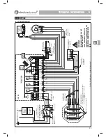
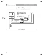
4-4.8 Motorized Valve
A 2 port motorised valve is supplied, this should be fitted in the heating flow from the
cylinder directly after the heating PRV take off and prior to any other take-offs. The valve
is wired as shown in figs. 3-3a and 3-3b.
The valve is normally closed to prevent gravity feed from the cylinder to the heating
system, when the pump starts the valve opens.
4-4.9 Bypass (not supplied)
An automatic bypass valve should be fitted between the flow and return of the heating
system, normally after the pump but before any radiator take offs. The valve must be set
to suit the pressure of the system, refer to manufacturers instructions.
4-4.10 Room Thermostat (not supplied)
A standard room thermostat with no built in timers or functions is recommended, e.g.
Honeywell T6360B or equivalent.
IMPORTANT
When a programmable room
thermostat is used it should only be
set to call for heat when ‘Economy
Tariff’ is available.
44444
Summary of Contents for Electrastream
Page 55: ...55 ...