25
✓
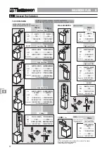
Supplied with Combistream
✓✓
Supplied with Combistream and Combi 65
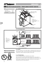
COLD
WATER
STORAGE
(Accumulator)
3
STOP COCK
DOUBLE CHECK VALVE
33
PRESSURE REGULATING VALVE
33
OUTSIDE TAP
CLEANSTREAM
3
DRINKING WATER
SERVICING VALVES
INST
INST
INST
INST
INSTALLA
ALLA
ALLA
ALLA
ALLATION - COMBISTREAM & COMBI 65 6
TION - COMBISTREAM & COMBI 65 6
TION - COMBISTREAM & COMBI 65 6
TION - COMBISTREAM & COMBI 65 6
TION - COMBISTREAM & COMBI 65 6
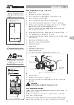
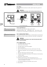
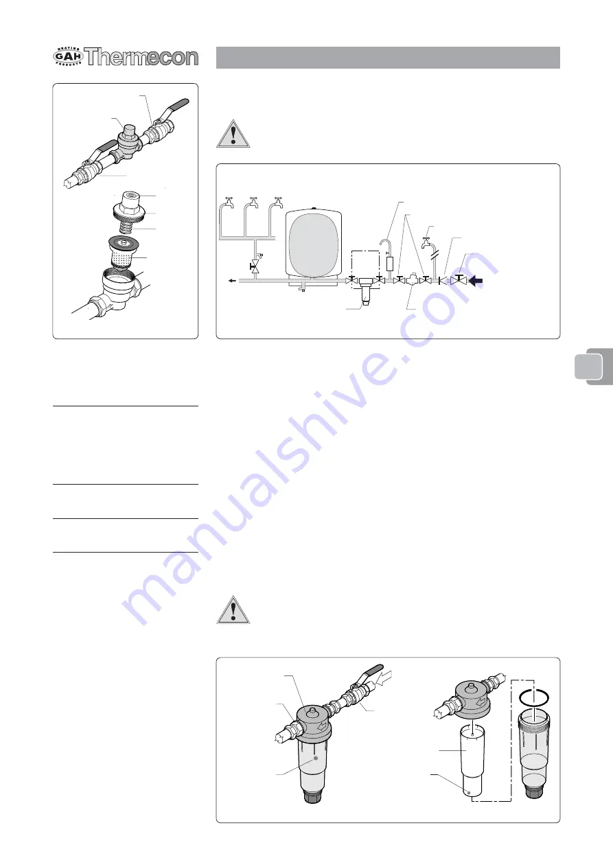
Before fitting the valve flush the supply pipework.
Periodically clean the filter and check or replace the cartridge with filter assembly.
WARNING
Take care not to alter the setting screw which is retained in the cap, it is
recommended to hold the spring in the cap as it is removed.
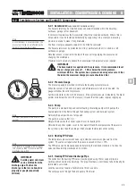
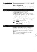
6-2.11 ‘Cleanstream’ Scale Prevention Unit
A ‘Cleanstream’ scale prevention device is supplied with the Combistream System. This
unit is effective in protecting the plumbing against both scale and corrosion.
It operates fully automatically by using the water flow to create a protective solution
which is deposited as a thin film on the inside of the pipes, cylinders and around heating
elements. The dose, which is proportional to the flow rate at approximately 5ppm, is
provided by a patented calibration system which is an integral part of the replaceable
cartridge.
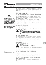
The Cleanstream has a red ball that is visible through the yellow bowl of the unit, when
this ball reaches the bottom of the cartridge it indicates that the cartridge should be
replaced.
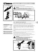
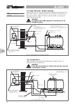
The Cleanstream unit should be fitted to the incoming main before the Accumulator and
after any drinking water outlets as shown in fig. 6-2d.
When a water softener is fitted, the Cleanstream unit should not be necessary.
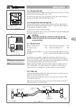
To enable cartridge change, a servicing valve should be fitted to the inlet side of the unit,
a non-return valve is included in the outlet of the unit - see fig. 6-2e.
IMPORTANT
Do not overtighten fittings as this could damage the plastic body.
Fit the unit with flow in the correct direction (as arrow).
Ensure the nut at the bottom of the unit is tight.
Allow at least 30mm under the unit for cartridge replacement.
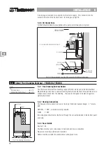
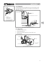
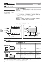
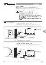
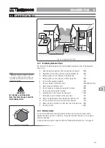
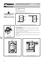
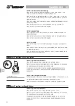
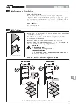
Fig. 6-2d Pressure Regulating Valve and Cleanstream Location
LABEL
CAP
SPRING
CARTRIDGE
WITH FILTER
SERVICING VALVE
PRESSURE
REGULATING VALVE
SERVICING VALVE
Fig. 6-2c Pressure Regulating Valve
Cleanstream Specification
Normal working pressure ..... 0.5-10 Bar
Pressure tested to ....................... 25 Bar
Temperature range ..................... 1-40°C
Max flow rate ........................ 3000 ltr/hr
Pressure loss ...................... 0.2-0.7 Bar
Cartridge life whole house .......... 6 mths
Cartridge life heating system .... 12 mths
Note
Replacement cartridges are available from
builders and plumbing merchants or from
GAH.
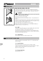
Fig. 6-2e Cleanstream Unit
RED BALL
CARTRIDGE
RED BALL
REPLACE CARTRIDGE WHEN
RED BALL IS AT THE BOTTOM
SERVICING VALVE
CLEANSTREAM UNIT
INTERNAL
NON-RETURN VALVE
66666

