


Pub. 42003-231A
M
ODELS
12587-101
&
-102
ICS
S
UBSET
E
XTENSION
C
ABLE
A
SSEMBLY
R
EPLACEMENT
K
IT
Page:
3 of 3
f:\standard ioms - current release\42003 kit manuals\42003-231a.doc
04/10
Installation as a Subset Extension Cord
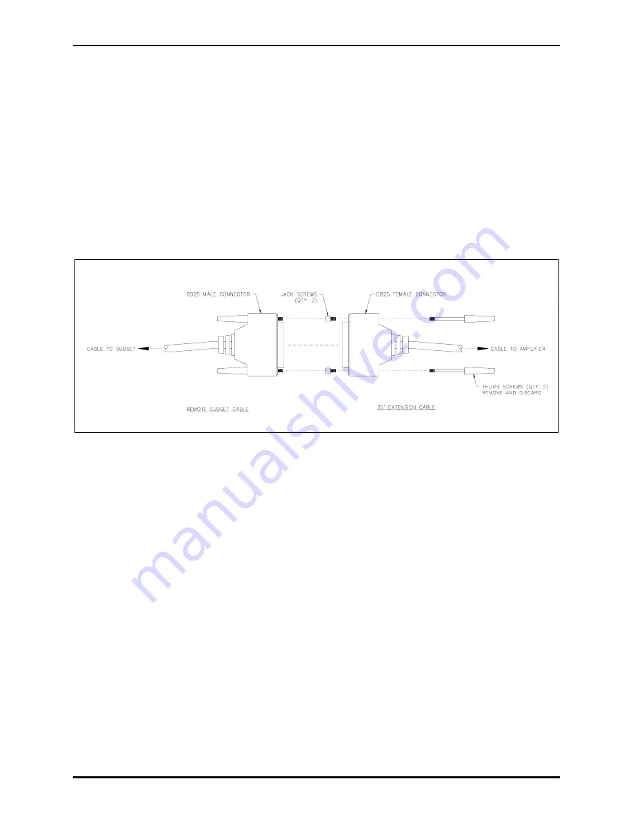
1. Arrange the extension cable so that the DB25 male connector is connected at the amplifier enclosure
or wall receptacle. Remove the thumb screws from the DB25 female connector. Install the two jack
screws provided. See Figure 2.
2. Plug the cable’s female DB25 connector into the remote subset cable’s (or an additional extension
cable’s) DB25 male connector and secure the connectors. Additional extension cables may be
connected in order to attain the necessary length. The maximum total length of the combined
extension cables is 100 feet.
3. When a cable is of sufficient length to reach the subset has been assembled, connect the female
DB25 connector at the end of the cable to the receptacle on the remote subset.
Figure 2. Installation as a Subset Extension


