Pub. 42004-455B
Model 352-101, 352-102, 352-103, & 352-104 Div. 1 SMART Hazardous Area Telephones Page 17 of 17
f:\standard ioms - current release\42004 instr. manuals\42004-455b.doc
02/13
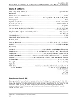
Specifications
TMA Compatibility profile type .......................................................................................... Type A Handset
Electrical
Minimum loop current (48 V dc only) ................................................................................................ 20 mA
Volume control ...................................................................... Five steps (0 dB, 5 dB, 10 dB, 15 dB, 20 dB)
Inter-digit pause .................................................................................................................................. 100 ms
Signaling tone (DTMF) ................................................................................................ 100 ms tone duration
Supervisory dc voltage ..................................................................................................... 24 V dc or 48 V dc
Network interface .......................................................................................................................... Loop Start
Auxiliary output (isolated solid state switch) .................................................................. 48 V dc @ 125 mA
28 V
RMS
ac @ 80 mA
RMS
Ring Relay PCBA output mechanical relay contact ............................................................ 250 V ac @ 5 A
30 V dc @ 5 A
Network signaling ............................................................................................................................... DTMF
Ringer Equivalence Number (REN) ....................................................................................................... 0.5B
Environmental
Operating temperature ..........................................................................
−
4º F to +140º F (
−
20º C to +60º C)
Humidity ...................................................................................................................... 90% non-condensing
Mechanical
Enclosure .............................................................................. Cast aluminum with aluminized lacquer paint
Handset Cord ....................................................... “G” style handset/PVC 6-foot extended length (standard)
Connections................................................................................ Internal screw-type barrier terminal blocks
Dimensions, Outside ............................... 10.25 W
12.25 H
9.50 D inches (260.3
311.1
241.3 mm)
Mounting .................................................. Wall or column, four 3/8-inch (10 mm) mounting feet with slots
Shipping weight ................................................................................................................ 30.0 lbs. (13.6 kg)
Net weight ......................................................................................................................... 28.0 lbs. (12.7 kg)
Approvals
NRTL listed ...................................................... Hazardous locations Class I, Division 1, Groups B, C, & D
(USA and Canada)
Class II, Division 1, Groups F & G
Class III, Division 1
Type 4X
T6 - Gas
T4A - Dust
User Instructions (USA)
This equipment has been tested and found to comply with the limits for a Class A digital device, pursuant to part 15 of the FCC
Rules. These limits are designed to provide reasonable protection against harmful interference when the equipment is operated in
a commercial environment. This equipment generates, uses, and can radiate radio frequency energy and, if not installed and used
in accordance with the instruction manual, may cause harmful interference to radio communications. Operation of this
equipment in a residential area is likely to cause harmful interference in which case the user will be required to correct the
interference at his own expense.


