background image

Pub. 42004-520A 

NEMA 4X VoIP Telephones 

Page 8 of 15 

P:\Standard IOMs - Current Release\42004 Instr. Manuals\42004-520A.docx 
03/17 

I/O 

Inputs 

Four clean dry-contact auxiliary inputs have been provided for customer use.  Terminations for these 
inputs are provided on terminal block P12.  Refer to Figure 7.  Connect each input between the desired 
input (

INPUT


1–4

) and common (

GND

) on terminal block P12.  Refer to the “Inputs” section of GAI-

Tronics Pub. 42004-481, “VoIP Telephone Configuration Guide” for programming instructions for these 
inputs. 

Table 2.  Auxiliary Inputs—Terminal Block P12 

Pin Label 

Function 

1 IN4 

Input 

2 COM  Common 

3 IN3 

Input 

4 COM  Common 

5 IN2 

Input 

6 COM  Common 

7 IN1 

Input 

8 COM  Common 


Inputs have an internal pull-up resistor and need to be 3.3 V dc tolerant. 

Outputs 

Two outputs have been provided for customer use.  Terminations for these outputs are provided on 
connector 

P2

 on the relay PCBA.  Refer to Figure 7. 

The function of each output is configurable.  Outputs can be configured for one of the following modes: 
On, Off, Pulse, Mute, Ring, Call, Connect, Hook, In Use, Ring Cadence, Ring Out, Page, Registered, or 
Emergency.  In some modes, the duration of the activation or on/off times can also be set.  Refer to the 
“Logic Settings” section of Pub. 42004-481, “VoIP Telephone Configuration Guide” for more details. 

Table 3.  Output Contacts—Connector P2 

Pin Label 

Description 

C2 

Common Output 2 

NO2 

Normally Open Output 2 

C1 

Common Output 1 

NO1 

Normally Open Output 1 


Relay capacity is 5 A at 30 V dc or 120 V ac. 

Summary of Contents for 354-700

Page 1: ...o ideal for use in areas that require a direct water spray hose down for cleaning purposes or where a non corrosive material is required The 354 70x Series Telephone is perfectly suited for areas cons...

Page 2: ...to peer configuration without the need for a LAN however a 10 100 Base T Ethernet network with a Sessions Initiation Protocol SIP server is required for systems containing three or more VoIP telephone...

Page 3: ...nnel NEVER install telephone wiring during a lightning storm Install a UL Listed lightning arrestor on any telephone installed where the telephone or telephone cable is at risk of being exposed to lig...

Page 4: ...it Security Hardware The Model 354 70x Series Telephone is vandal resistant with the front panel attached to its enclosure with security screws A GAI Tronics Model 233 001 Security Screwdriver sold se...

Page 5: ...holes located on the mounting flanges with 3 8 inch M8 hardware The recommended entry is via the enclosure bottom to prevent moisture from dripping onto the connection terminals When mounting the encl...

Page 6: ...l push button and ringer The handset rests on a cradle which has a magnetic reed switch to signal an off hook condition See Figure 3 Figure 3 NEMA 4X VoIP Telephone Internal The Model 354 70x NEMA 4X...

Page 7: ...Figure 5 This configuration presents the easiest access for troubleshooting and setting adjustments 2 Plug the incoming Cat5 data line to the network RJ45 cable jack on the underside of the VoIP circu...

Page 8: ...2 6 COM Common 7 IN1 Input 1 8 COM Common Inputs have an internal pull up resistor and need to be 3 3 V dc tolerant Outputs Two outputs have been provided for customer use Terminations for these outp...

Page 9: ...WG is typical Status Indication Power The power LED located on the VoIP PCBA illuminates when power is applied to the telephone Refer to Figure 7 for the location Heartbeat The heartbeat LED located o...

Page 10: ...13 1 36 Nm External Controls Handset ReceiverVolumeControl A push button switch is provided on the front panel for adjustment of the handset receiver volume When pressed it decreases the volume gain f...

Page 11: ...for the network prior to installation Assign a local ID domain proxy and registrar Assign a host name The host name provides identification of the different VoIP PCBAs on the network Test Verify that...

Page 12: ...ndset on hook Monitoring and Reporting Each telephone can recognize and generate several hardware and configuration fault condition alarms These alarms can be signaled to a remote site using three met...

Page 13: ...uts not operational Check the output connections Verify the outputs are properly configured Cannot make or receive calls Check the connection of the LAN cable Verify that power is applied to the unit...

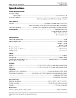
Page 14: ...dB Analog earpiece gain Default 20 dB Setting 2 12 dB Setting 3 0 dB Frequency response 250 Hz to 6500 Hz Frequency response flatness 3 dB minimum THD 1 kHz 1 minimum Inputs Keypad 3 4 matrix Push but...

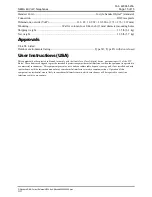
Page 15: ...User Instructions USA This equipment has been tested and found to comply with the limits for a Class A digital device pursuant to part 15 of the FCC Rules These limits are designed to provide reasonab...

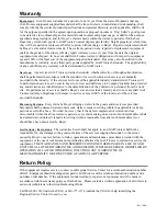
Page 16: ...of the Contractor s personnel from the work site Re performance of services shall be Buyer s sole and exclusive remedy and in no event shall GAI Tronics warranty obligations with respect to services e...

Reviews: