Auteldac 5
10
3.4 Connections and Cabling
IMPORTANT WARNING:-
ISOLATE MAINS AND TELEPHONE LINE OUTSIDE THE
HAZARDOUS AREA BEFORE OPENING THE CASE.
ALL TERMINALS MUST BE CONNECTED IN ACCORDANCE WITH
THIS INSTALLATION GUIDE. ANY DEVIATION FROM THIS MAY
RESULT IN AN UNSAFE INSTALLATION AND
VIOLATE THE
CONDITIONS OF THE CERTIFICATION.
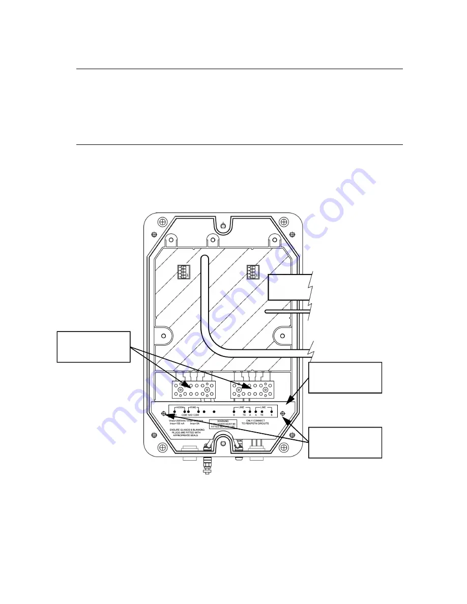
The connections to the Auteldac 5 are made via 2 terminal blocks below the
main PCB. The cabling between the entry glands and the terminal blocks is
covered by a terminal cover, secured by 2 screws as shown. Remove this
cover to allow access to the terminals.
The terminal cover must be secured in place before re-assembling the
telephone prior to use.
The terminal cover provides the required isolation
between the cabling in the rear section and the circuitry in the front section
and is critical to the product's certification.
Terminal cover
screws
Terminal blocks
Terminal cover
Summary of Contents for Auteldac 5
Page 31: ...Auteldac 5 30 6 2 1 1 CE Declaration of Conformity...
Page 35: ...Auteldac 5 34...


