Pub. 43004-027B
Model IDA1000A DC Remote Adapter Installation and Service Manual
Page 7 of 24
P:\Radio Products-Current Release\43004\43004-027B\43004-027B.docx
06/18
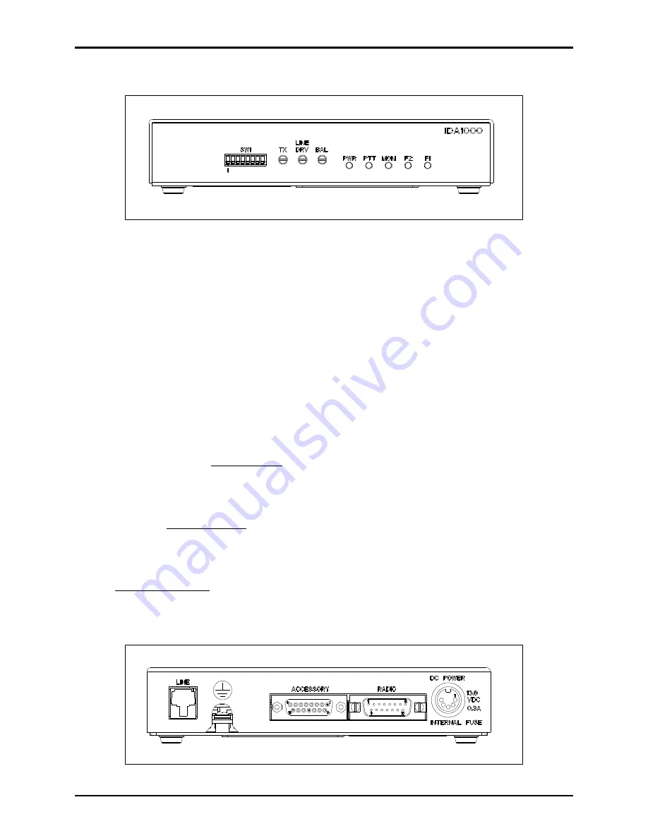
Front Panel
Figure 1. Front View of the Model IDA1000A DC Remote Adapter
Programming Switches
The programming switches (
SW1
) are used to set up and interface with the radio system. They are
numbered from left to right when viewed from the front.
Front Panel LEDs
The
PWR
LED indicates the remote adapter is on. The
PTT
LED illuminates when a valid transmit
request has been decoded. The
MON
(timed or constant monitor) LED illuminates when the Model
IDA1000A is in monitor mode. The
F1
and
F2
LEDs indicate current frequency and/or other functions.
Line Level Adjustments
TX Adjustment
The
TX
adjustment pot sets the level of the transmit audio to that required to properly modulate the base
station’s transmitter (see the Transmit Level section for adjustment instructions).
Line DRV Adjustment
The
L
INE
DRV
adjustment is used to set the telephone (audio) line level or “drive” to the remote desk set
or console (see the Line Drive Level section for adjustment instructions).
BAL Adjustment
The balance potentiometer (
BAL
) allows optimizing the hybrid RX to TX isolation of the internal hybrid
(see the Balance Adjustment section for adjustment instructions).
Rear Panel
Figure 2. Rear View of the Model IDA1000A DC Remote Adapter


