55
03/12
Theory of Operation
General Desk Set Overview
The IPE2500A is a multi-processor design employing state-of-the-art DSP technology to achieve superior
performance over typical analog and single-processor designs. This allows for ultimate flexibility in
audio processing.
The heart of the design consists of U1, the DSP; and U3, the microcontroller. The DSP is responsible for
audio processing of receive and transmit audio. This includes notch and line filtering, tone detection,
tone generation, audio level compression and setting, and audio routing.
The microcontroller is responsible for controlling the functions of the DSP, programming, the LCD
display, keyboard scanning, support of the relay, dc, and multi-line select modules and general I/O and
general operational functions.
Receive Audio
Receive audio is presented to the desk set through the line transformer providing for the necessary load.
The audio is buffered and switched by U14. U14 controls the source of the receive audio: line1 for two-
wire, or line 2 for four-wire operation.
The appropriate receive audio is then passed to the gain stage, consisting of U21 and U12. U12 provides
the compression mechanism used by the DSP to keep the receive audio below the maximum level of
approximately –6 dBm. This compressor can be disabled using the desk set diagnostics. After the
receive audio has been properly compressed, it is passed to A/D section of U15 where it is converted to
digital for use by the DSP and also to P400-12 for data conditioning.
The input impedance for two-wire operation is controlled by U10. When U10-1 is asserted, the input
impedance is 560 ohms. When U10-1 is unasserted, the input impedance is bridging.
Speaker Audio
Speaker audio is originated from the DSP in digital format. The DSP combines the receive audio, which
is notched for tone control operation, side-tone, and beep tones to generate the speaker audio.
The speaker audio is converted to analog using the D/A section of U17. It is then passed through the
volume control stage consisting of U13 and U22 before being passed to the handset earpiece and the
speaker amplifier, U18.
The microcontroller or the DSP can mute the speaker amplifier. The microcontroller mutes the speaker
audio using U5-C8, in cases such as parallel mute or the user muting via a key press. The DSP uses a
speaker squelch algorithm to squelch the speaker when no audio is being output to the speaker. This
squelch will remain open for two seconds after no audio is present. The DSP then mutes the speaker
using U1-88.
Summary of Contents for IPE2500A
Page 69: ...63 03 12 Circuit Boards...
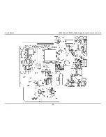
Page 70: ...Circuit Boards IPE2500A and IPE2500A MLS Paging Encoder Desktop Controller 64...
Page 71: ...IPE2500A and IPE2500A MLS Paging Encoder Desktop Controller Circuit Boards 65...
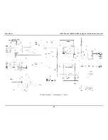
Page 73: ...67 03 12 Schematics...
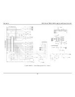
Page 80: ...Schematics IPE2500A and IPE2500A MLS Paging Encoder Desktop Controller 74 Schematic Sheet 7...
Page 86: ...Schematics IPE2500A and IPE2500A MLS Paging Encoder Desktop Controller 80...

