IPE2500A and IPE2500A-MLS Paging Encoder/Desktop Controller
Theory of Operation
57
03/12
DC Control Module (not compatible with MLS operation)
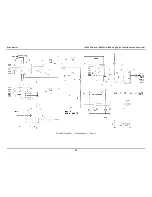
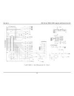
The reference designators listed in this section refer to the dc control schematics unless otherwise stated.
The dc control module provides a method of generating dc control currents on line 1 and detecting line
voltages to restrict transmission during a parallel transmit. The microcontroller provides the dc control
current information to the dc control module in a serial format to U505.
Using the resistor ladder consisting of LR1A–LR6B, this information is converted into a dc voltage.
This dc voltage then provides a control reference, using U503 and Q507, to the comparator circuit
consisting of U502 and U501.
U501 then causes Q500 and T500 to generate the necessary switch voltage to achieve the desired line
current. This line current is then converted to a voltage reference using U502 and R532 that is fed back
and compared again to the reference voltage provided by Q507.
The direction of the current, positive or negative, is controlled by U505-7. This signal causes either
U510 or U511 to be switched on. If U510 is switched on, then U511 is switched off and the current is
output on J13-8 and returned on J13-7.
If U511 is switched on then U510 is switched off and the current is output on J13-7 and returned on J13-
8. Before any current can be output and returned, U505-7 must be high. This, in turn, provides a ground
to Q512 and Q513 that allows U510 or U511 to be switched on.
Relay Control Module (not compatible with MLS operation)
The reference designators listed in this section refer to the relay control schematics unless otherwise
stated.
The relay control module is used to provide closures out via relays and sense closures via closures to
ground. The microcontroller provides closure-out information and reads closure-in information via serial
data. Closure outputs are controlled by the data in U701. Closure senses inputs are read from U702.
To provide a closure on relay 1, the microcontroller asserts U701-15. This, in turn, drives the
corresponding Q701 that provides the ground for the coil of K701. To provide a closure sense input on
input 1, J701-5 must be grounded.
This, in turn, is latched into U702 by the microcontroller where the microcontroller takes the appropriate
action.
Summary of Contents for IPE2500A
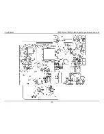
Page 69: ...63 03 12 Circuit Boards...
Page 70: ...Circuit Boards IPE2500A and IPE2500A MLS Paging Encoder Desktop Controller 64...
Page 71: ...IPE2500A and IPE2500A MLS Paging Encoder Desktop Controller Circuit Boards 65...
Page 73: ...67 03 12 Schematics...
Page 80: ...Schematics IPE2500A and IPE2500A MLS Paging Encoder Desktop Controller 74 Schematic Sheet 7...
Page 86: ...Schematics IPE2500A and IPE2500A MLS Paging Encoder Desktop Controller 80...

