Pub. 42004-787L2A
SP2 Zone 2/22 Weatherproof Handset/Speaker Amplifier Station
Page 18 of 21
\\dc1vc1fs05\GTCPRODDOCS_86H27G1-FS\Standard IOMs - Current Release\42004 Instr. Manuals\42004-787L2A.docx
10/17
Maintenance
Troubleshooting
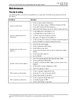
The following table is provided to aid qualified service personnel in troubleshooting problems with the
SP2 Station.
Problem
Solution
station not functional
check wiring and cable terminations
check power supply voltage at
TB3
on Termination PCBA
Power LED on Main PCBA illuminated
Heartbeat LED blinking once per second for normal operation
network communication not
functional
verify
LNK
LED on main PCBA is off
verify
SPD
LED on main PCBA is off
verify IP connection settings using telnet
ping station IP address from an admin PC
verify network switch settings for Internet Group Management
Protocol (IGMP) snooping and multicast filtering
handset receiver audio is too
high/low
adjust the Receiver Volume
check potentiometer
R37
setting
check handset connections
check cable terminations between the Termination and Main
PCBAs
check hookswitch operation
replace handset
speaker volume is too high/low
adjust the Speaker and 600-ohm Audio Output Volume
check potentiometer
R36
setting
P2 and P3 Termination PCBA jumper positions incorrect (see
Figure 5)
check speaker wiring configuration on TB1
replace the speaker or driver
RTU output is not functional
verify no monitored output faults exist
check fuse
F1
on the Termination PCBA
check connected device operation
RTU input does not function
verify no monitored input faults exist
check RTU Inputs on
TB2
check connected device operation


