background image

Page 

9 of 14

GAI-Tronics 6-Channel Radio

Pub.: 42004-325A

f:\standard ioms - current release\42004 instr. manuals\42004-325a.doc
10/00

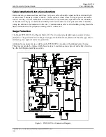
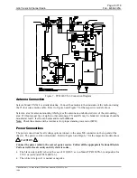
Figure 7.  TP4514SYN-6 Connection Diagram

Antenna Connection

Select a Model CN3614 or similar antenna.  Connect the antenna to the underside of the radio unit using
the 25-foot coax antenna cable.  Refer to Figure 6 and Figure 7 for the respective models above.

Select an area for antenna mounting which gives the antenna an unobstructed view of the surrounding
area.  Without proper line of sight to other antenna(s), TX and RX may be hindered.  Antennas should be
mounted at least 3 feet from I-beams and metal bulkheads.

Note:

  Check the antenna with a watt meter for proper standing wave ratio (SWR).

Power Connections

The power connections for all voltage options connect to the same MS connector on the top end of the
chassis.  The power cord is not included.  Refer to Figure 6 and Figure 7 for the respective models above.

CAUTION

Connect the power cable to the correct power source.  Follow all the appropriate National Electric
Code as well as local county and city electric codes.


The black wire (pin B) is hot in the case of 110/220 V ac (on Model TP4512SYN-6) and positive for
270 V dc (on Model TP4514SYN-6).


The white wire (pin C) is neutral or negative.

Summary of Contents for TP4512SYN-6

Page 1: ...aker Connector 3 Microphone Connector 3 Antenna Connector 3 Channel Selector Switch 3 Radio Transceiver Module 3 Interface PCBA 4 Jumper Table 4 Pot 1 4 Wide Range 110 220 V AC 270 V DC Power Supply P...

Page 2: ...ent 10 Speaker Output Adjustment 11 Operation 11 Initiating Calls 11 Receiving Calls 11 Controls 11 Maintenance 12 Ordering Replacement Parts 12 Service and Repair 12 Troubleshooting the 6 Channel Rad...

Page 3: ...er TP4514SYN 6 120 V ac Frequencies programmed by customer TP4512SYN 6FR 110 220 V ac 270 V dc Frequencies programmed at factory TP4514SYN 6FR 120 V ac Frequencies programmed at the factory Features a...

Page 4: ...rs are located on the top of the unit The antenna connection is on the underside of the unit and remains easily accessible when the unit is mounted Refer to the outline drawings below The standard pow...

Page 5: ...key C Mic Lo D 15 V dc power AntennaConnector The antenna connector is a coax cable connector Channel Selector Switch The channel selector switch on the top of the unit provides the capability to easi...

Page 6: ...for the location of the pot Refer to the Installation section for instructions for speaker output adjustment Wide Range 110 220 V AC 270 V DC Power Supply PCBA This switch mode power supply features h...

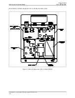
Page 7: ...6 Channel Radio Pub 42004 325A f standard ioms current release 42004 instr manuals 42004 325a doc 10 00 For locations of internal components refer to the diagram shown below Figure 4 Internal Componen...

Page 8: ...nd can radiate radio frequency energy and if not installed and used in accordance with the instruction manual may cause harmful interference to radio communications Operation of this equipment in a re...

Page 9: ...d to ground through 100K of resistance 7 When soldering be sure the soldering iron is grounded with a grounded tip 8 Prior to connecting jumpers replacing circuit components or touching CMOS pins if t...

Page 10: ...ctor such as porcelain tubes or flexible tubing in addition to the insulation on the wire Communications cables and in building wiring should be listed and marked for the purpose according to NEC Arti...

Page 11: ...nna s TX and RX may be hindered Antennas should be mounted at least 3 feet from I beams and metal bulkheads Note Check the antenna with a watt meter for proper standing wave ratio SWR Power Connection...

Page 12: ...or similar cast speaker Install the cast speaker by plugging it into the appropriate connector on the top of the radio Programming The radio transceiver module contains programmable features such as...

Page 13: ...ith units which have identical CTCSS or DPL programming Refer to the transceiver module manual Ritron Pub DTX MRM for details InitiatingCalls 1 To initiate a call press the microphone button Always al...

Page 14: ...492 1212 select option 2 from the menu to obtain a Return Authorization number published repair prices and shipping instructions Note A purchase order or credit card number will be required prior to p...

Page 15: ...screws on the left of the battery mounting bracket 3 Slide the bracket to the left and lift it out of the key hole slot 4 Reverse the process to install the new battery Performance Specifications Col...

Page 16: ...ries Description Part No Microphone Noise Canceling MI2895 Cast Aluminum Speaker 651301 102 Antenna with 25 foot Coax Cable and Connector CN3614 UHF Ground Plate CH3272 6 Channel Radio to GAI Tronics...

Reviews: