PLEASE TURN PAGE FOR INSTALLATION STEPS 8, 9 & 10
6.
3.
4.
5.
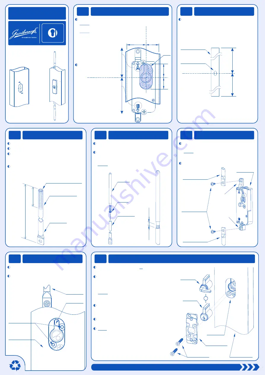
Insert Lock into section
Cut and thread Tubes
Fit Bolt Tips
Attach Tubes to Lock
E TH
L
C
IS
Y
P
C
A
E
C
R
K
E
A
S
G
A
IN
E
G
L
P
(PK0013) Double Shoot-Bolt instructions (Trade A4) R2.cdr
7.
Attach Fixing Plate and Cylinder to Lockbody
Mark the position of the cylinder barrel on your section.
NOTE: Make sure to equal or exceed the minimum
dimensions shown below.
NOTE: The orientation of the lock
is important with regard to the
cutout dimensions, and the rod
preparation. Be sure to note
whether the “A” or “B”
symbol on the lockcase
is facing towards the
top of the door/window.
Cut out the opening.
22.0
19.0
22.0
minimum
14.7
minimum
R10.0
lock barrel
centerline
lock barrel
centerline
dimension
A
dimension
B
1.
Prepare the cutouts
DOUBLE SHOOT-BOLT
Austral Lock
MADE IN AUSTRALIA BY
Illustrated fitting
instructions
MOUNTING
CUTOUTS
(One face only)
ASSEMBLED
PRODUCT
2.
Calculate Tube length
Use the equations below to calculate the
length of
drive tube A
and
drive tube B
corresponding to dimension A and dimension B
(from Step 1).
door / window
lock cutout
barrel
centerline
DRIVE TUBE
A
= dimension
A
- 147mm
DRIVE TUBE
B
= dimension
B
- 172mm
(tube length is measured from end to end - see Step 3)
dimension
A
dimension
B
Carefully cut the tubes to length.
Debur the cut ends of the two tubes.
Use a
1/4” BSW thread
tap to cut an internal
thread to a depth of 30mm (do this to
both tubes).
Chamfer
the inside edge of the tube using a
countersink or large drill bit.
drive tube
1/4” BSW
internal thread
chamfer inside edge
DRIVE
TUBE LENGTH
30mm
Ensure the black
o-ring
is in position
on each bolt tip as shown below.
Thread the two
bolt tips
into the two
drive tubes
until there is
5mm
of thread
still visible on the
bolt tips
.
NOTE: This provides space for fine adjustment
once the window or door is fitted.
drive tube
bolt tip
o-ring
5mm
Place the
onto the corresponding
bosses of the
lock slides
as shown.
NOTE: Ensure
is assembled
onto
lockslide A
. and
drive tube B
is
assembled onto
lockslide B
.
drive tubes
drive tube A
Secure using the two
G6 x 3/8 AB washer
screws
provided.
lock body
drive tube A
drive tube B
G6 x 3/8 AB
washer screws
lockslide A
lockslide B
Slide the
lock assembly
into the
door/window
section
.
the
lock body
are visible through the cutout
as shown below.
Position the assembly so the two bosses on
door/window
section
bosses
lock body
drive tube
Install the
keyed cylinder
or
thumbturn cylinder
into the
cylinder opening
in the
lock body
.
Fit the
fixing plate
over the
cylinder
and align
the two bosses on the
fixing plate
with those
on the
lock body
.
then rotate the
thumbturn lever
through it’s full
o
movement (180 ) and back to a position at
o
90 to the
cylinder
as shown.
NOTE: You will need to position the
fixing plate
by rotating it over the
thumbturn lever
from the side.
If using the
thumbturn cylinder
, install it as above
using the two
G8 x 1 fixing screws
provided.
Secure the
fixing plate
to the
lock body
TEST: Use
key
or
thumbturn lever
to test
the operation of the lock. If the
drive rods
do not extend and retract properly, check
your assembly and repeat the steps above.
or
keyed
cylinder
fixing plate
lock body
fixing screws
thumbturn
cylinder
door/window
section


