GS2011M Low Power WiFi Module Data Sheet
GS2011M Architecture
Wireless LAN and System Control Subsystem
GS2011M-DS-001211, Release 0.9
Confidential Preliminary
35
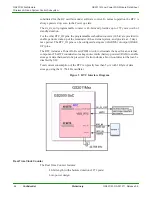
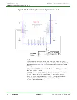
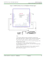
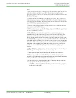
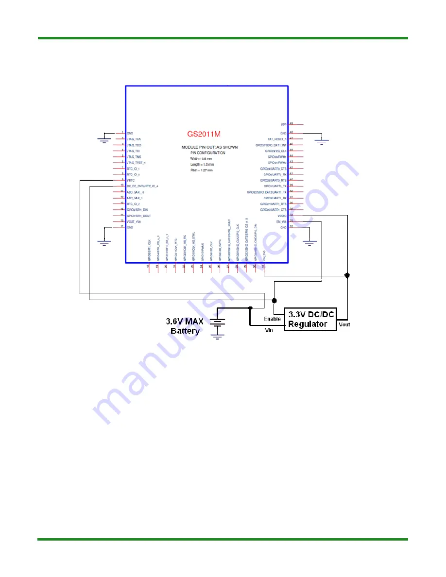
Figure 6 GS2011MIx Battery Powered with Optimized Standby Support
Notes:
1. This connection applies for designs (typically battery operated) using
GS2011MI module and want to optimized standby (lowest current consumption)
state of the module. In this connection it is important to note the following:
2. Input voltage to VRTC must always be ON to keep the RTC powered so that
the 32KHz crystal is running.
3. VDDIO and VIN_3V3power should be OFF during this state.
Recommendation is to use DC_DC_CNTL to also control the unit supplying the
voltage to VDDIO and VIN_3V3
4. DC_DC_CNTL must be connected to EN_1V8 to so that the internal 1.8V
regulator gets turned OFF when system goes to standby state (i.e.
DC_DC_CNTL is de-asserted).


