background image

GS2K-SKB-HW-UG-001278, Release 1.0

33

Chapter 3  Initial Board Connections and Configuration

This chapter describes how to quickly administer initial settings and to run the TLS 
application on a GainSpan

®

 GS2200M based Starter Kit Board.

The following sections are covered in this chapter:

Connecting the Board to a Communication Port, page 33

Powering ON the Starter Kit Board, page 35

3.1 Connecting the Board to a Communication Port

There are a few basic connections that must be addressed in order to communicate with the 
GS2200M SKB.

Perform the following:

1. Plug the 

mini-USB

 cable into the 

USB

 port on the board, and plug the other end of the 

mini-USB

 cable into a 

USB

 port on a computer.

2. From the Windows desktop, open the Device Manager as shown in 

Figure 2, page 33

The USB Serial port is listed under Ports (COM & LPT).

Figure 2   Windows Device Manager Properties

Summary of Contents for GS2200M

Page 1: ... 11 23 2016 Copyright 2016 GainSpan All rights reserved GS2200M Module SKB Hardware User Guide GS2K SKB HW UG 001278 Modules GS2200M Board Revisions SKB 1 2 GainSpan 802 11b g n Ultra Low Power WiFi Series Modules ...

Page 2: ...roducts including liability or warranties relating to fitness for a particular purpose merchantability or infringement of any patent copyright or other intellectual property right GainSpan products are not authorized for use as critical components in medical lifesaving or life sustaining applications GainSpan may make changes to specifications and product descriptions at any time without notice Tr...

Page 3: ...Release 1 0 11 23 2016 Copyright 2016 GainSpan All rights reserved ...

Page 4: ......

Page 5: ...Release 1 0 11 23 2016 Copyright 2016 GainSpan All rights reserved ...

Page 6: ......

Page 7: ...nd Safety Specifications 31 2 3 1 Electrical Guidelines 31 2 3 2 Connecting Power 31 Chapter 3 Initial Board Connections and Configuration 33 3 1 Connecting the Board to a Communication Port 33 3 2 Powering ON the Starter Kit Board 35 Appendix A GS2200M Starter Kit Board Specifications 37 A 1 GS2200M Module Specifications 37 A 2 GS2200M Starter Kit Board LEDs 38 A 3 GS2200M Starter Kit Board Senso...

Page 8: ...GS2200M Starter Kit Board Hardware User Guide 8 GS2K SKB HW UG 001278 Release 1 0 ...

Page 9: ...le Starter Kit board that supports the GS2200M Module Refer to the following sections Revision History page 10 Audience page 10 Standards page 10 Documentation Conventions page 11 Documentation page 14 References page 16 Contacting GainSpan Technical Support page 17 Returning Products to GainSpan page 18 Accessing the GainSpan Portal page 19 ...

Page 10: ...owing new information listed in Table 1 page 10 Audience This manual provides instructions on how to setup and use the GS2000 based module starter kit board along with component description jumper settings board specifications and pinouts Standards The standards that are supported by the GainSpan modules are IEEE 802 11b g n Table 1 Revision History Version Date Remarks 1 0 November 2016 Initial R...

Page 11: ...ne and sample source code AT XXXX Proportional font description Gives specific details about a parameter Data DATA UPPERCASE Variable parameter Indicates user input Enter a value according to the descriptions that follow Each uppercased token expands into one or more other token lowercase Keyword parameter Indicates keywords Enter values exactly as shown in the command description Square brackets ...

Page 12: ...on of the element that immediately follows it multiple times Do not enter as part of the command AA NN can be expanded to 1 01 1 02 1 03 A B C D IP address IPv4 style address 10 0 11 123 X X X X IPv6 IP address IPv6 style address 3ffe 506 1 Where the represents all 0x for those address components not explicitly given LINE End to line input token Indicates user input of any string including spaces ...

Page 13: ...erstanding a feature or references to material not available in the manual Alert Alerts you of potential damage to a program device or system or the loss of data or service Caution Cautions you about a situation that could result in minor or moderate bodily injury if not avoided Warning Warns you of a potential situation that could result in death or serious bodily injury if not avoided Electro St...

Page 14: ...000 Based Module Use Case Reference Guide for using Serial to WiFi AT Commands Provides an easy to follow instructions on how to use the AT commands in different scenarios GS2200 S2W APP PRG RG 001208 GainSpan Serial to WiFi Adapter Application Programmer Reference Guide Provides a complete listing of AT serial commands including configuration examples for initiating maintaining and evaluating Gai...

Page 15: ...edback comments and suggestions so that we can improve the documentation You can send your comments by logging into GainSpan Support Portal If you are using e mail be sure to include the following information with your comments Document name URL or page number Hardware release version if applicable Software release version if applicable ...

Page 16: ...2 Module Firmware and Programming Utilities Serial to WiFi S2W based firmware Temperature and Light Sensor TLS based firmware For use with GS2011M EVB GS2200 EVB and GS2200M SKB only Firmware Release Notes GSFlashprogram utility for programming the modules Smart Phone Applications Smart Phone applications for iOS and Android to evaluate and demonstrate the Temperature and Light Sensor TLS firmware...

Page 17: ...rt Question tab 6 Select Add New Question 7 Enter your technical support question product information and a brief description The following information is displayed Telephone number contact information by region Links to customer profile dashboard and account information Links to product technical documentation Links to PDFs of support policies Table 6 GainSpan Technical Support Contact Informatio...

Page 18: ...nt Your name organization name telephone number and fax number Description of the failure 4 The support representative validates your request and issues an RMA number for return of the components 5 Pack the component for shipment Guidelines for Packing Components for Shipment To pack and ship individual components When you return components make sure they are adequately protected with packing mate...

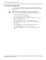
Page 19: ...rted tab to view a Quick Start tutorial on how to use various features within the GainSpan Portal 4 Click the Actions tab to buy evaluate or download GainSpan products 5 Click on the Documents tab to search download and print GainSpan product documentation 6 Click the Software tab to search and download the latest software versions 7 Click the Account History tab to view customer account history 8...

Page 20: ...GS2200M Starter Kit Board Hardware User Guide 20 GS2K SKB HW UG 001278 Release 1 0 This page intentionally left blank ...

Page 21: ...ed WiFi or RF expertise or for those seeking faster time to market as it reduces RF design time and removes the burden of testing and certification The module incorporates a full WiFi and TCP IP networking stack a full suite of networking services including WiFi provisioning DHCP TLS SSL HTTP S mDNS DNS CoAP XML JSON and over the air firmware upgrade The GainSpan module is easily designed into emb...

Page 22: ... and provides access to all of its IO signals via various connectors An Arduino compatible connector may be used to connect an Arduino shield or to use the SKB as an Arduino shield Pmod compatible SPI UART and I2C connectors provide for connecting additional peripherals A USB serial port provides for flash programming and debug terminal output input The JTAG header may be used to attach a JTAG deb...

Page 23: ...ther uses once the application code is running 7 I O Enable Jumpers J10 Peripheral Enable Jumpers Install jumper to enable signal on peripheral connector s Only install jumpers as needed to avoid hardware conflicts 8 Program Button SW2 Push button to put the module in PROGRAM mode if pressed while the RESET button is released or power is switched on This button is available for other uses once the...

Page 24: ...nt Switch J21 The switch selects between Active coarse 100mA V and Sleep fine 125uA V current measurement NOTE This switch should be in active mode for normal operation The module cannot operate normally with the switch in sleep mode The switch should only be switched to the Sleep position after the module has entered deep sleep standby or hibernate mode to measure ultra low power levels 19 JTAG C...

Page 25: ...rs J1 J2 J3 J4 Arduino shield connectors The SKB can be configured to be the host default or a shield See GS2200M SKB Arduino Connector Pinouts page 46 24 Test Points TP4 TP5 Bench power supply connection points Connect a 3 3V supply for bench powering and set the power source selection jumpers to use the bench supply as the power source Note The on board power switch is bypassed when using a benc...

Page 26: ...GS2600M Starter Kit Board Hardware Overview GS2200M Starter Kit Board Hardware User Guide Starter Kit Board Software 26 GS2K SKB HW UG 001278 Release 1 0 This page intentionally left blank ...

Page 27: ...uirements The following sections are covered in this chapter Preparing for Starter Kit Board Setup page 27 Setting Up the GS2200M Based Starter Kit Board page 30 Power Guidelines Requirements and Safety Specifications page 31 2 1 Preparing for Starter Kit Board Setup This section describes how to prepare for setting up the GS2200M based SKB It discusses the following topics Site Preparation page 2...

Page 28: ... provided throughout this manual Comply with all applicable safety requirements practices and standards Refer to Appendix A GS2200M Starter Kit Board Specifications page 37 After setting up the board protect your equipment by using an ESD approved grounding strap whenever handling board components 2 1 3 Environmental Requirements The following Environmental Requirements must be taken into consider...

Page 29: ...escribed in the following steps 1 Remove the packing slip from the shipping box Use this paper work to validate the contents 2 Prepare to remove the board from the shipping box Remove cabling from the box and set it aside Remove any documentation from the box and set it aside 3 Carefully lift the board from the shipping container 4 Remove the protective ESD bag from the evaluation board 5 Set all ...

Page 30: ...ng Up the GS2200M Based Starter Kit Board This section describes how to perform the following installation tasks Place the SKB on a secure flat surface Connect all cabling Apply and verify power to the SKB 2 2 1 Placing the GS2200 SKB on a Tabletop The board must be set on a sturdy tabletop or workbench environment Use safe practices when placing boards next to each other ...

Page 31: ...lling Keep the board area clear and free of dust during and after installation The board operates safely when it is used in accordance with its marked electrical ratings and product usage instructions 2 3 2 Connecting Power The board gets power from a computer USB port via the mini USB cable The board is designed to operate on only one USB connection Power can also be supplied from batteries a 3 3...

Page 32: ...tting Up the Starter Kit Board GS2200M Starter Kit Board Hardware User Guide Power Guidelines Requirements and Safety Specifications 32 GS2K SKB HW UG 001278 Release 1 0 This page intentionally left blank ...

Page 33: ...t page 33 Powering ON the Starter Kit Board page 35 3 1 Connecting the Board to a Communication Port There are a few basic connections that must be addressed in order to communicate with the GS2200M SKB Perform the following 1 Plug the mini USB cable into the USB port on the board and plug the other end of the mini USB cable into a USB port on a computer 2 From the Windows desktop open the Device ...

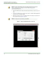
Page 34: ...select the Tera Term VT terminal emulation application teraterm_utf8 4 58 or later to install 5 Open the Tera Term VT from your desktop and select the serial port associated with the evaluation board see Figure 3 page 34 Figure 3 Connect Evaluation Board to a Serial Port NOTE The FTDI Virtual COM port driver can enumerate devices to any one of a number of COM ports It is necessary to find the COM ...

Page 35: ... Figure 4 page 35 Figure 4 Select Serial Port COM port Settings 3 2 Powering ON the Starter Kit Board 1 Turn the PROGRAM RUN switch to the RUN position 2 Turn the ON OFF switch to the ON position 3 The TLS boot messages will display within the Tera Term VT window see Figure 5 page 35 Figure 5 Serial to WiFi Application Ready NOTE For Temperature and Light Sensor TLS application set the Baud Rate t...

Page 36: ...tarter Kit Board Hardware User Guide Powering ON the Starter Kit Board 36 GS2K SKB HW UG 001278 Release 1 0 Refer to the GainSpan Temperature and Light Sensor TLS Demo Application Note for more information about using and understanding the TLS application ...

Page 37: ...re Description Radio Protocol IEEE 802 11b g n RF Operating Frequency 2 4 GHz Supported Data Rates 72 65 58 43 29 22 14 7 Mbps 802 11n 54 48 36 24 18 12 9 6 Mbps 802 11g 11 5 5 2 1 Mbps 802 11b Antenna External Antenna u FL connector or On board Antenna Operating Temperature 20oC to 70oC Security Protocols WPA WPA2 Personal WPA WPA1 Enterprise PEAP EAP FAST EAP TLS EAP TTLS WEP TLS SSL Client and ...

Page 38: ...nSpan GS2200M WiFi Module Data Sheet Table 10 GS2200M SKB LEDs LED SKB Description Power D4 Green Illuminates when 3 3V output of the switch is powered This LED can be disabled for low power operation by removing the LED EN jumper J16 UART TX D3 Amber This LED flickers when the SKB is transmitting on the serial port LED1 D2 Green Software controlled LED Note The LED does not draw any power when it...

Page 39: ...00uA respectively The switch is make before break such that it can be switched from Active to Sleep position after the GS2000 has entered standby or hibernate without causing a brownout RESTORE Button SW1 Push button switch to restore the board to factory default settings The button causes the previous firmware image to be restored if pressed while the RESET button is released or power is switched...

Page 40: ...whose output is connected to J12 Header J12 selects between USB 5V or battery power sources The battery power source is via a boost regulator prior to the connection to J12 The third header J13 selects between the bench supply input test point or the source selected via J12 and J19 When the J13 jumper is in the BENCH position the position of the first two jumpers is irrelevant The bench input must...

Page 41: ...ndby or hibernate 7 VDDIO VRTC load switched by DC_DC_CTL powers down when the GS2200M goes into standby or hibernate 8 1 8V_SW regulated 1 8V supply switched by the DC_DC_CTL on the load side of the power measurement circuit powers down when the GS2200M goes into standby or hibernate 9 3 3V_SW 3 3V load switched by DC_DC_CTL provides switched power prior to the power measurement circuit to supply...

Page 42: ...GS2200M Starter Kit Board Hardware User Guide GS2200M Starter Kit Board Power 42 GS2K SKB HW UG 001278 Release 1 0 This page intentionally left blank ...

Page 43: ...e SPI peripheral connector J5 is a Pmod Type 2A compatible interface It supports attaching a SPI slave or master device The SPI role of the GS2200M is configured via jumper settings on header J20 Table 14 page 44 gives the pin assignments Table 13 JTAG Cortex Debug Connector Pin Assignments SKB Pin No Signal Name Description 1 VDDIO Digital IO Supply Voltage 2 JTAG_TMS Joint Test Action Group TAP ...

Page 44: ...SB port Alternatively either UART can be left unconnected by omitting jumpers for that port The USB port is always configured for peripheral mode such that the board will always be a peripheral to the host PC it is connected to Table 14 SPI Connector Pin Assignments SKB Pin No Signal Name Description 1 SS Slave Select GPIO33 SDIO_DAT3 SPI0_CSn_0 2 MOSI GPIO36 SPI0_DOUTGS2200M is SPI Master Out Jum...

Page 45: ... pin assignments Table 15 UART Connector Pin Assignments SKB Pin No Signal Name Description 1 CTS GPIO26 U1CTS M GS2200M configured as Host on UART1 GPIO27 U1RTS M GS2200M configured as Peripheral on UART1 GPIO25 U0RTS M GS2200M configured as Peripheral on UART0 2 TX GPIO32 U1TX GS2200M configured as Host on UART1 GPIO03 U1RX GS2200M configured as Peripheral on UART1 GPIO00 U0RX GS2200M configured...

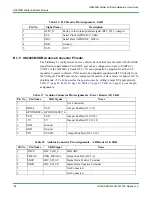
Page 46: ...ble 18 page 46 Table 19 page 47 Table 20 page 47 gives the pin assignments Table 16 I2C Header Pin Assignments SKB Pin No Signal Name Description 1 ALM_N Extra pin for interrupt alarm signal RTC_IO_2 jumper 2 SCL Serial Clock GPIO9 I2C_CLK 3 SDA Serial Data GPIO8 I2C_DATA 4 GND Ground 5 VSN VCC Table 17 Arduino Connector Pin Assignments Power Header J3 SKB Pin No Pin Name SKB Signal Notes 1 Not Co...

Page 47: ... configured as Host on UART1 GPIO26 U1CTS M GS2200M configured as Peripheral on UART1 GPIO24 U0CTS M GS2200M configured as Peripheral on UART0 Table 20 Arduino Connector Pin Assignments IO Low Header J1 SKB Pin No Pin Name SKB Signal Description 8 RTCIO4 RTC_IO_4 Jumper Enabled J10 3 4 7 GPIO31 PWM2 GPIO31 PWM2 6 GPIO30 PWM1 GPIO30 PWM1 5 GPIO10 PWM0 GPIO10 PWM0 4 CTS GPIO26 U1CTS M GS2200M config...

Page 48: ...GS2200M Starter Kit Board Hardware User Guide GS2200M Starter Kit Board Pinouts 48 GS2K SKB HW UG 001278 Release 1 0 ...

Reviews: