background image


Please read the warnings and instructions carefully in the present manual since they are concerning the 

important indications and safety of operation and maintenance. The Manufacturer is in no way responsible 
for  eventual  damages  to  persons,  animals  or  equipments  caused  by  improper,  erroneous,  incorrect  and 
unreasonable application. 

Usage notice.


1.


Please read the operator’s instruction manual before using this equipment. 

2.


Instruction book must be read carefully when using air hydraulic Jack. 

3.


The  manufacturer  reserves  the  rights  to  improve  equipment  without  giving  prior  notice  to  buyer  in 
advance. 

4.


The  operator  shall  read  and  operate  the  Jack  according  to  the  manual,  paying  special  attention  to  the 
safety warnings. Bodily inquiry or death may occur if the safety warnings are ignored. 

5.


Please do not damage or disassemble the safety valve. 

6.


please place the air hydraulic Jack in the middle of heavy loading object when using. 

7.


During and after lifting the vehicle, make sure to properly position jack stands (supports). 

8.


Please make sure there is plenty of room to operate the Jack according to the manual. 

9.


When lifting or lowering, please check and make sure no body is under the heavy loading object. 

10.


When lowering, the operation rod must be kept in the lowest position to avoid damages.


Application:


Air  hydraulic  jack  is  a  newly-type  lifting  equipment.  It  utilizes  compressed  air  to  promote  booster 

cylinder,  to  make  the  hydraulic  oil  which  is  stored  in  oil  tank  infuse  into  oil  cylinder  to  move  hydraulic 
cylinder up & down. It adopts the machinery design combination of hydraulic pressure with great advantages 
of delicate design, small dimension, convenient moving, wide scope of usage, strong jacking capacity and 
low lifting part. It is a convenient lifting equipment and low labor intensity of automobile  manufacturing, 
repairing, engineering mechanism or heavy-facility. 
 

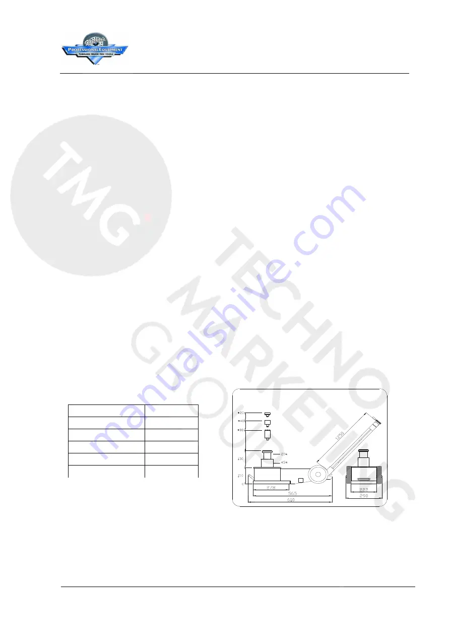
Specification & Parameter. 


Model No. 

GT-4532 

Jacking Capacity 

45t/20t 

Air Pressure 

8-12 bar 

Lowest Height 

150mm 

Hoisting Height 

130mm 

Weight 

46 kg 


Summary of Contents for GT4532

Page 1: ...INSTRUCTIONS FOR GT4532...

Page 2: ...ing object when using 7 During and after lifting the vehicle make sure to properly position jack stands supports 8 Please make sure there is plenty of room to operate the Jack according to the manual...

Page 3: ...ting please estimate the weight of vehicle to avoid overloaded The life of Jack will be affected strongly if it is overloaded 7 When lifing position the equipment under the strongest centre point of t...

Page 4: ...ng tool when using It can not be used as a supporting tool Without any secured stands or solid supports on the suitable area under raised vehicle to assure security any operators are strictly prohibit...

Page 5: ...be used in the flat floor Don t use it in slope or inclined floor Don t use it in slope or inclined floor When lifting please support the landed wheels by some objects to avoid the vehicle moving afte...

Page 6: ...ce spare parts 3 Check and repair cylinder Booster pump does not work 1 One way valve or spring is broken see picture B 2 Booster piston or booster cylinder is broken 3 Air pressure is not enough air...

Page 7: ...il nicht und entfernen Sie es nicht von der Ausr stung 6 Bitte setzten Sie den lufthydraulischen Wagenheber beim Einsatz mittig unter das Schwerlastobjekt 7 Bitte stellen Sie sicher nach dem Anheben d...

Page 8: ...rn lesen Sie bitte sorgf ltig den Aufkleber Warnhinweise der auf der Bedienungsstange angebracht ist 5 Stellen Sie beim Anheben einige Unterstellb cke oder feste Auflagen an geeignete Stellen unter da...

Page 9: ...organg durch das Begrenzungssystem automatisch beendet b Bedienen Sie den Griff des Handventils im Gegenuhrzeigersinn um den Absenkvorgang auszuf hren Der Wagenheber senkt sich bei angemessener Ausleg...

Page 10: ...k nnen Legen Sie immer einige St tzen unter das Rad um ein Weg und Abrutschen zu verhindern wenn der Wagenheber angehoben oder abgesenkt wird bitte lesen Sie sorgf ltig den Aufkleber Warnhinweise auf...

Page 11: ...det werden Zusammen mit dem Wagenheber sollten einige Unterstellb cke oder feste Auflagen verwendet werden Stellen Sie beim Anheben sicher dass der Verl ngerungsstempel richtig auf das Schwerlastobjek...

Page 12: ...berpr fen und Ersatzteile einbauen 3 Zylinder berpr fen und reparieren Boosterpumpe funktioniert nicht 1 Einwegventil oder Feder defekt siehe Abb B 2 Booster Kolben oder Booster Zylinder ist defekt 3...

Page 13: ...e krik in het midden van de last te plaatsen wanneer u deze gebruikt 7 Nadat het voertuig is opgetild onmiddellijk assteunen plaatsen 8 Zorg voor het tillen dat het betreffende voertuig niet kan beweg...

Page 14: ...n en moeren 8 Gelieve het handvat van de hendel vast te houden bij het gebruik van de krik om de krik stabiel te houden en beschadigingen te voorkomen 9 Zorg er voor dat de krik steeds voorzien is van...

Page 15: ...gebruikt om te ondersteunen Zonder assteunen of andere solide steunen is het verboden onder zich onder het voertuig te bevinden Gelieve aandachtig het WARNINGS label op de krik te lezen 2 Gebruik de...

Page 16: ...d blijven vast te zetten om beweging van het voertuig bij het tillen te vermijden Deze krik is enkel geschikt om lasten te tillen en niet om te ondersteunen Gebruik daarom altijd assteunen na het till...

Page 17: ...r is stuk zie foto B 5 Booster piston or booster cilinder is stuk 6 Er is te wienig druk luchtslang los of luchtinlaat is niet aangesloten 4 Controleer en vervang het nodige onderdeel 5 Controleer en...

Page 18: ...et 4 M8 Screw 1 4 M10 Spring Gasket M10 Screw 1 Operation Rod FL B9 B10 C C40 D 1 1 Boosting System O Ring 1 1 7 10 4 11 12 Windpipe Windpipe Adaptor Windpipe Windpipe M10 Gasket M10 Bolt 1 Extension...

Page 19: ...Ring Piston 1 1 1 2 1 1 Piston 1 C16 C15 1 2 C13 C14 1 C12 Screw plug 1 C17 C20 1 O Ring 1 1 Adaptor 3 Gasket C11 1 O Ring 1 1 1 1 1 1 1 1 Hydraulic Intergration Fuel Return Thimble Fuel Return Piston...

Page 20: ...D13 D12 D11 D15 D14 D16 D20 D19 D18 D17 D1 C20 D22 D21 D25 D24 D23 D27 D26 4 4 2 C14 C15 1 Screw plug O Ring Screw plug O Ring Gasket Windpipe M8 Bolt A24 2 D7 C49 Adaptor 2 D2 Oil Cylinder Drawings 1...

Page 21: ...asket 4 1 2 2 2 Truckle 1 B21 B16 1 2 Screw Outer Retainer Ring Adaptor Nail Protected Plate B18 B19 Adaptor B22 Label 1 Frame Drawings B4 B5 B6 B4 B5 B6 B16 B17 B16 B22 B1 B18 B20 B19 B21 Picture D N...

Page 22: ...1 Adaptor Main Body FL A23 1 Handle Cover Windpipe Windpipe Filter 2 2 2 Screw A20 A21 A22 2 Handle Screw 1 1 A14 A13 A15 Picture E No PART NAME QTY No PART NAME QTY No PART NAME QTY Windpipe A12 A22...

Page 23: ...d Valve Cover of Reversing Valve O Ring Shaft Valve Core Screw Conversion Base 1 1 1 1 2 1 Label A1 8 A1 10 A1 11 A1 4 A1 3 A1 2 A1 1 1 A1 5 1 A1 6 2 A1 7 1 2 A1 12 2 A1 1 Hand Valve O Ring Spring Gas...

Page 24: ...ily Air compressor Quick adaptor Adaptor Adaptor Quick adaptor 3 1 Pls choose the air compressor with air consumption of above 0 6 m min for air hydraulic Jack 2 The inside diameter or outlet pipe air...

Page 25: ...GAITHER NOTES...

Page 26: ...ed States Armed Forces just to name a few Gaither supplies products to customers in over 100 countries selling through exclusive and nonexclusive distributors Gaither Tool Company Inc is headquartered...

Reviews: