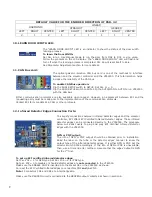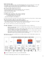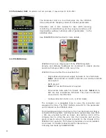
8
7.
Additional I/O Board:
8.
Encoder card:
9.
Encoder:
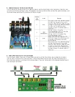
Additional I/O board, 2500-3055, is optional. If used, this
board will be connected to the connector J7 of the main board
2500-3050. The additional features of this board are:
-
Inputs for the Heavier, and Narrower doors.
Elevator controller must provide command signals
to the Heavy and Narrow inputs to use the functions of
the parameters sets of the Heavier and Narrower doors.
Set Par. 199 = 0 if Narrower door is used.
-
Edges Timeout:
Once the infrared detector edge is
obstructed, and after a delay set by Par. 197, the
Edges Timeout relay will be activated and held for
an interval of time set by Par. 206. Should the
edges timeout relay be used for Nudging application,
it must be subject to the elevator fire service codes.
-
DOL of the narrower door is selectable between the
Regular output DOL on the main board or the
AUX/NARROWER output on the Additional I/O board.
Set Par. 204 = 1 if only the regular DOL output is used.
Set Par. 204 = 0 if both the AUX/NARROWER output
and regular DOL output are used.
-
AUX2 relay is provided as a spare output and is controlled
by Par. 68. If the door position is less than the value
set in Par. 68, the AUX2 relay will be activated.
-
Buzzer: once the infrared detector edge is obstructed, and
after a delay set by Par. 198, the output of the Buzzer will
be activated. Buzzer operation is controlled by Par. 205.
Par. 205 = 0 : Disable
Par. 205 = 1 : Enable in Continuous mode
Par. 205 = 2 : Enable in Pulsating mode
The Buzzer volume control is on the board. Turn the Pot. R3
clockwise for louder sound.
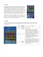
The optical galvanic isolation encoder card is a means to interface between the
encoder and The MCU (Micro Controller Unit). This total isolation helps enhance
the reliability and safety of the feedback system.
RJ12 mating gold-plated connectors are also used to maximize the conductivity
between the encoder and MCU.
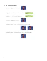
To verify encoder direction:
Press the
key, run the door in manual mode or physically move the door by hand, and watch the LCD
display. If the door closes and the count decreases, or the door opens and the count increases, then the encoder
direction is correct. Otherwise, change parameter 42 from 1 to 2 or vice versa. The table below provides the default
values of par. 42.
VOLT
PULSE
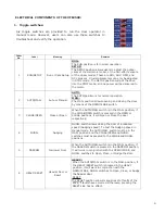
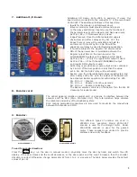
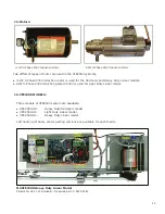
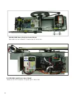
Two different types of encoder are used in
VFE2500 door operators. Model 2500-3057
encoder is used for the straight motor. Model
2500-3058 encoder is used for the geared
motor. These encoders are utilized to provide
distance and velocity feedback.
Model:2500-3057
Model:2500-3
5/
8
Summary of Contents for MOVFE 2500
Page 1: ...2500 3069 1 888 425 2262 2500 3069 ELECTRICAL...
Page 2: ...Rev 1 10 20 I...
Page 24: ...19 6 DEFAULT PARAMETERS 19...
Page 26: ...21 FAULTS AN EXAMPLE OF FAULTS DISPLAY COUNTERS 21...
Page 27: ...22 USER LIST 22...
Page 28: ...23 23...
Page 29: ...24 24...
Page 30: ...25 25...
Page 31: ...26 MAXIMUM CLOSE SPEED AND FORCE 26...
Page 32: ...27 ECI DEFAULT PARAMETER SETS 27...
Page 34: ...29 SPEED PROFILES OF THE VFE2500 FOR NORMAL DOOR 29...
Page 35: ...30 SPEED PROFILES OF THE MOVFE2500 FOR HEAVY DOOR 30...
Page 36: ...31 SPEED PROFILES OF THE MOVFE2500 FOR NARROW DOOR 31...
Page 91: ...Rev 10 20 85...
Page 92: ......


