10
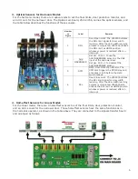
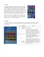
Test the detector edges:
- Obstruct the infrared detector edges. The DETECTOR EDGES LED, near the Re-Open relay, should be ON.
- The REOPEN relay should be activated to send the REOPEN flag to the elevator controller.
- The elevator controller will send the Door Open command signal to the VFE2500 to REOPEN the door.
The LED of the Open Input module should be ON.
If the detector edges function does not work.
- Check the manual for correct connections between edges and the VFE2500.
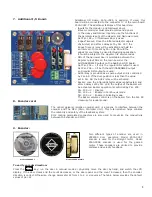
- Check for 24VDC between 0V and +V on either CN4 or CN5.
- Repeat testing the detector edges.
If it still does not work. Then,
-Jump 0V to LCSE on either CN4 or CN5 connector for NPN type.
-Jump +V to LCSE on either CN4 or CN5 connector for PNP type
- The DETECTOR EDGES LED should be OFF.
- The RE-OPEN Relay should be activated.
Otherwise, the problem is in the VFE2500.
If the above step works as described, turning ON the detector edges LED, then the problem is in detector edges.
If the infrared detector edges have intermittent problems:
- Check continuity of the TX and RX cables of the infrared detector edges.
- If the cables are good, but the problem still exists, then check the Earth Ground connection to the edges.
- Lower the Carrier Frequency in Par. 1 gradually until problems are resolved.
Note! The lower carrier frequency will create more audible noise.
The major advantages of connecting ECI certified infrared detector edges via VFE2500 are:
-
Eliminates an extra power supply for the detector edges, resulting is less mounting, less wiring, and
fewer components to fail.
-
The REOPEN relay that is used for infrared detector edges interface provides 2 more safety features
to reopen the door: Over-speed and over-torque detections.
-
When the VFE2500 door operator and the interface circuit with the infrared detector edges are
provided by ECI. ECI can provide the best technical support.
-
ECI provides users with an Additional I/O board to assist customers with Nudging feature. This
additional I/O board only works with ECI Certified Infrared Edges
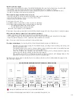
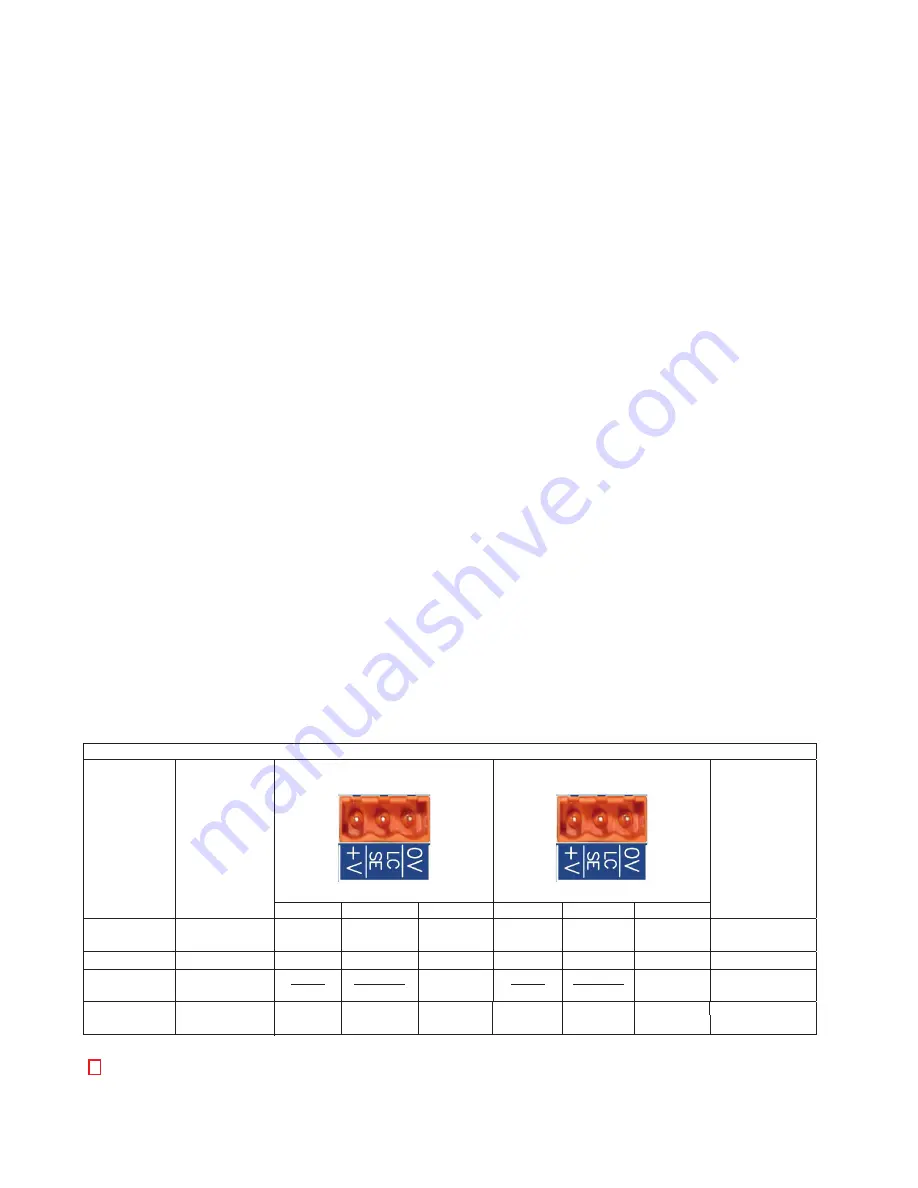
The table below assists users to identify the colors, numbers of each wire from infrared detector edges to the
VFE -2500 door operator.
ECI CERTIFIED INFRARED DETECTOR EDGES WIRE COLORS
ECI
P/N
MFG.
TX(CN5)
RX(CN4)
CONNECTION
BETWEEN
TX & RX
V+ LCSE 0V V+ LCSE 0V
906-
RED
121(
906-3020
TRITRONICS
RED
WHITE
ORANGE
NONE
906-3030
FORMULA
SYSTEMS
BLUE
1
BROWN
2
GREEN
YELLOW
BLUE
1
BROWN
2
GREEN
YELLOW
NONE
&RQQHFWDQDGGLWLRQDOZLUHIURP9WRDWUXH($57+*5281'
ECI Certified Infrared Edges and Enable IC U5 are available through ECI, Inc.
BROWN
GREEN
YELLOW
BLUE
BROWN
GREEN
YELLOW
BLUE
NONE
VERSION 2
FORMULA
SYSTEM
Ƈ
BLACK
BLUE
BLACK
GREEN
JANUS
E40 32
RED
10
Summary of Contents for MOVFE 2500
Page 1: ...2500 3069 1 888 425 2262 2500 3069 ELECTRICAL...
Page 2: ...Rev 1 10 20 I...
Page 24: ...19 6 DEFAULT PARAMETERS 19...
Page 26: ...21 FAULTS AN EXAMPLE OF FAULTS DISPLAY COUNTERS 21...
Page 27: ...22 USER LIST 22...
Page 28: ...23 23...
Page 29: ...24 24...
Page 30: ...25 25...
Page 31: ...26 MAXIMUM CLOSE SPEED AND FORCE 26...
Page 32: ...27 ECI DEFAULT PARAMETER SETS 27...
Page 34: ...29 SPEED PROFILES OF THE VFE2500 FOR NORMAL DOOR 29...
Page 35: ...30 SPEED PROFILES OF THE MOVFE2500 FOR HEAVY DOOR 30...
Page 36: ...31 SPEED PROFILES OF THE MOVFE2500 FOR NARROW DOOR 31...
Page 91: ...Rev 10 20 85...
Page 92: ......


