4
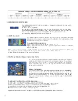
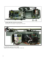
ELECTRICAL COMPONENTS OF THE VFE2500:
1.
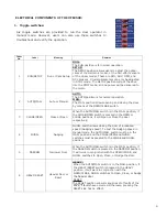
Toggle switches:
Order
No.
Label Meaning
Remarks
1
RUN/SETUP
Run or Cam Setup
RUN:
The RUN position is for normal operation.
SETUP:
The SETUP position allows users to adjust the optical
cams of the Harmonic model, or the hall-effect sensors
of the Linear model. These are DOL, AUX, DPM, and
DCL sensors . Crucial parameters can only be adjusted
in STOP mode. The SETUP position will put the drive
into the STOP mode, and no power will be delivered to
the motor.
2
AUTO/MAN.
Auto or Manual
AUTO:
The AUTO position is for normal operation.
MAN.:
The MAN. position allows opening and closing the door
by means of the OPEN/CLOSE switch.
3
CLOSE/OPEN
Close or Open
When the AUTO/MAN. switch is in the MAN. position, if
the CLOSE/OPEN switch is pressed in the OPEN or
CLOSE positions, it will Open or Close the door
respectively.
4 NUDG.
Nudging
NUDG. switch allows closing the door at a reduced
speed (Nudging speed). To test the Nudging speed in
Manual mode, the AUTO/MAN. switch must be in the
MAN. position and the CLOSE/OPEN and NUDG.
switches must be pressed to the CLOSE and NUDG.
positions.
5
NARROW
Narrower Door
When the AUTO/MAN. switch is in the MAN. position, if
the NARROW switch is pressed in the NARROW position,
it will work in conjunction with the OPEN/CLOSE, and
NUDG. switches to Open, Close, or Nudge the door.
6 HEAVY/RESET
Heavier Door or
Reset
HEAVY:
When the AUTO/MAN. switch is in the MAN. position, if
the HEAVY/RESET switch is pressed in the HEAVY
position, it will work in conjunction with the
OPEN/CLOSE, NUDG. switches to Open, Close, or Nudge
5(6(7
The RESET position allows manual reset of faults of the
drive, if faults have occurred. Otherwise, pressing the
RESET side has no effect.
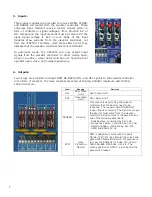
Six toggle switches are provided to run the door operator in
manual mode. However, users can also use these switches to
troubleshoot and verify the operation.
the heavier door.
4
Summary of Contents for MOVFE 2500
Page 1: ...2500 3069 1 888 425 2262 2500 3069 ELECTRICAL...
Page 2: ...Rev 1 10 20 I...
Page 24: ...19 6 DEFAULT PARAMETERS 19...
Page 26: ...21 FAULTS AN EXAMPLE OF FAULTS DISPLAY COUNTERS 21...
Page 27: ...22 USER LIST 22...
Page 28: ...23 23...
Page 29: ...24 24...
Page 30: ...25 25...
Page 31: ...26 MAXIMUM CLOSE SPEED AND FORCE 26...
Page 32: ...27 ECI DEFAULT PARAMETER SETS 27...
Page 34: ...29 SPEED PROFILES OF THE VFE2500 FOR NORMAL DOOR 29...
Page 35: ...30 SPEED PROFILES OF THE MOVFE2500 FOR HEAVY DOOR 30...
Page 36: ...31 SPEED PROFILES OF THE MOVFE2500 FOR NARROW DOOR 31...
Page 91: ...Rev 10 20 85...
Page 92: ......


