


SMART CUT 1000
18
4.
4.
4.
4. OPERATION
OPERATION
OPERATION
OPERATION
4.1
4.1
4.1
4.1 Layout Of The Front And Rear Panel
Layout Of The Front And Rear Panel
Layout Of The Front And Rear Panel
Layout Of The Front And Rear Panel
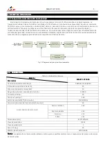
3
380V
1
2
3
4
5
6
7
8
9
10
11
12
13
14
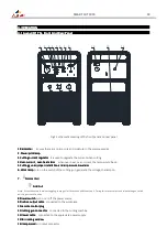
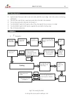
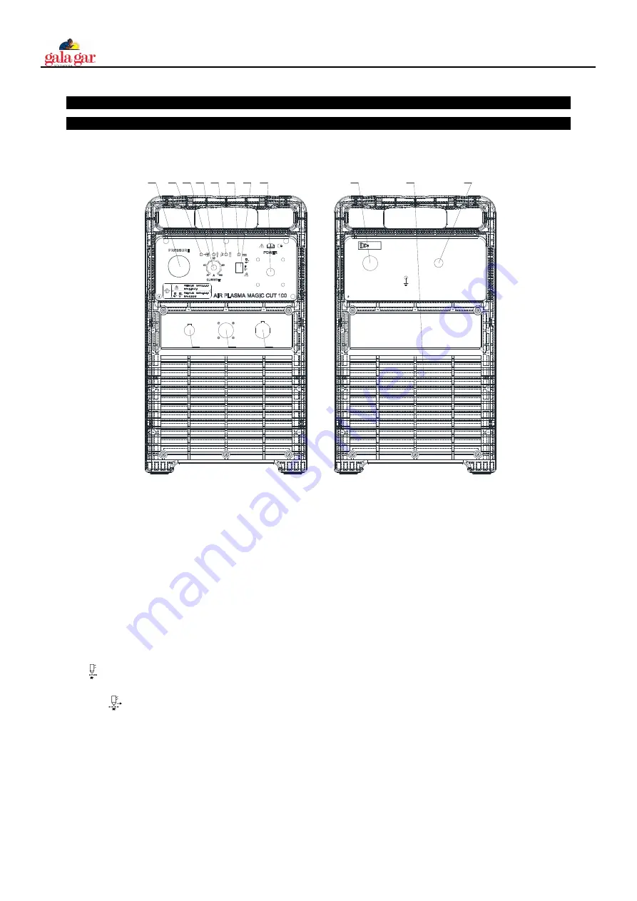
Fig 4.1 schematic drawing of the front panel and rear panel
1.Barometer
1.Barometer
1.Barometer
1.Barometer ensure there are no impurity and moisture in the compressed air
2. Power pilot lamp
2. Power pilot lamp
2. Power pilot lamp
2. Power pilot lamp
3.Cutting current regulator
3.Cutting current regulator
3.Cutting current regulator
3.Cutting current regulator it is used to regulate the current when cutting.
4.Over
4.Over
4.Over
4.Over----current , over
current , over
current , over
current , over----heat alarm
heat alarm
heat alarm
heat alarm when over-heat, over-current, the lamp would be on.
5.Cutting gun improper installation and air pressure low alarm
5.Cutting gun improper installation and air pressure low alarm
5.Cutting gun improper installation and air pressure low alarm
5.Cutting gun improper installation and air pressure low alarm
6. W
6. W
6. W
6. Work lamp
ork lamp
ork lamp
ork lamp turn on the switch of the cutting gun, generate the voltage, the lamp on
7.
7.
7.
7.
Normal Cut
Normal Cut
Normal Cut
Normal Cut
Grid Cut
Grid Cut
Grid Cut
Grid Cut
Note: When these two functions toggling, check gas for 10 seconds and then stop it. During this process, press and release the gun switch
quickly, gas check finishes.
8.Power switch
8.Power switch
8.Power switch
8.Power switch turn on or off the power source
9.Positive output cable
9.Positive output cable
9.Positive output cable
9.Positive output cable connected to the workpiece
10.remote control plug
10.remote control plug
10.remote control plug
10.remote control plug
11.Cutting gun connector
11.Cutting gun connector
11.Cutting gun connector
11.Cutting gun connector connected to the cutting machine
12.Power cable
12.Power cable
12.Power cable
12.Power cable connected to the appreciate power supply
13.fan cooling window
13.fan cooling window
13.fan cooling window
13.fan cooling window
14.Compressed
14.Compressed
14.Compressed
14.Compressed air output connector
Summary of Contents for 223001000C
Page 26: ......
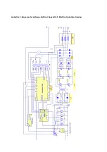
Page 27: ...Apéndice 1 Esquema del sistema eléctrico Appendix 1 Electrical principle drawing ...
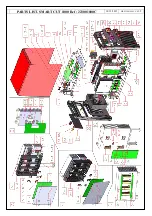
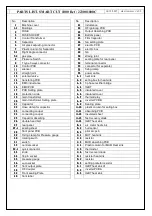
Page 28: ...PARTS LIST SMART CUT 1000 Ref 223001000C 14 12 2015 HR 223001000C V0 1 2 ...
Page 30: ......
Page 31: ......


