


SMART CUT 1000
23
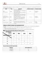
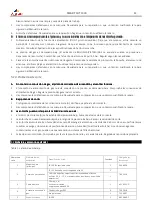
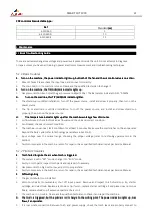
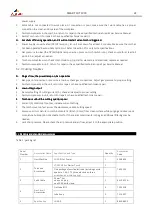
CNC control cable selectable type:
CNC control cable selectable type:
CNC control cable selectable type:
CNC control cable selectable type::
:
:
:
Ref
Ref
Ref
Ref
Standard
(m)
(m)
(m)
(m)
6.310.660
5
6.310.660-D
10
6.310660-E
15
5.
Maintenance
Maintenance
Maintenance
Maintenance
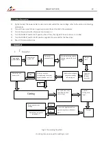
5.1
Basic Troubleshooting Guide
Basic Troubleshooting Guide
Basic Troubleshooting Guide
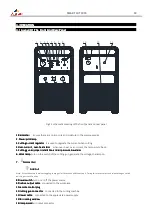
Basic Troubleshooting Guide
There are extremely dangerous voltage and power levels present inside this unit. Do not attempt to diagnose
or repair unless you have had training in power electronics measurement and troubleshooting techniques.
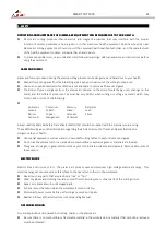
5.1.1 Basic troubles
E.
E.
E.
E.
Turn on the machine, the power indicator
Turn on the machine, the power indicator
Turn on the machine, the power indicator
Turn on the machine, the power indicator lights up
lights up
lights up
lights up, but both of the fan and the
, but both of the fan and the
, but both of the fan and the
, but both of the fan and the air control valve
air control valve
air control valve
air control valve is no
is no
is no
is no action
action
action
action....
1.
Absent Phases. Please check the input lines, and connect it correctly.
2.
The
main board in the machine is break
. Please ask the qualified technician to change it.
F.
F.
F.
F.
Turn on the machine,
Turn on the machine,
Turn on the machine,
Turn on the machine, the TIP/GUN/GAS
the TIP/GUN/GAS
the TIP/GUN/GAS
the TIP/GUN/GAS indicator
indicator
indicator
indicator lights up.
lights up.
lights up.
lights up.
1.
Gas pressure is too low. Adjust the gas pressure to 65psi/4.5bar. The Barometer indicate to 0.45~0.5MPa.
G.
G.
G.
G.
Turn on the machine,
Turn on the machine,
Turn on the machine,
Turn on the machine, the TIP/GUN/GAS
the TIP/GUN/GAS
the TIP/GUN/GAS
the TIP/GUN/GAS indicator
indicator
indicator
indicator glitte
glitte
glitte
glitterrrr....
1.
The shield cup is unfitted installation, Turn off the power source, install and screw it properly, then turn on the
power source.
2.
The Tip or electrode is unfitted installation, Turn off the power source, and install and screw shield cup
properly, then turn on the power source.
H.
H.
H.
H.
The t
The t
The t
The temperature
emperature
emperature
emperature indicator
indicator
indicator
indicator lights up
lights up
lights up
lights up after the machine working a few of minutes
after the machine working a few of minutes
after the machine working a few of minutes
after the machine working a few of minutes....
1.
Air flow blocked, check for blocked air flow around the unit and correct condition.
2.
Fan blocked, check and correct condition.
3.
The machine is over-heat, let it cool down for at least 5 minutes. Make sure the machine has not been operated
beyond the Duty Cycle (refer to technology parameters in Section 2).
4.
Input voltage over the normal range, choosing the proper voltage (refer to technology parameters in the
Section).
5.
Faulty components in the machine, return for repair or have qualified technician repair per Service Manual.
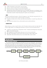
5.1.2 Pilot arc troubles
E.
E.
E.
E.
Torch fail
Torch fail
Torch fail
Torch failed
ed
ed
ed to ignite the arc when torch
to ignite the arc when torch
to ignite the arc when torch
to ignite the arc when torch is
is
is
is trigger
trigger
trigger
triggered.
ed.
ed.
ed.
1.
The system is set in “SET” mode, change it to “RUN” mode.
2.
Faulty in torch parts, inspect torch parts and replace it if necessary.
3.
Gas pressure is too high or too low, adjust it to proper state.
4.
Faulty components in the machine, return for repair or have qualified technician repair per Service Manual.
F.
F.
F.
F.
Difficult ignit
Difficult ignit
Difficult ignit
Difficult igniting
ing
ing
ing
1.
The gas distributor is un-installed
2.
Worn torch parts (consumables), shut off input power. Remove and inspect torch shield cup, tip, starter
cartridge, and electrode. Replace electrode or tip if worn; replace starter cartridge if end piece does not move
freely; replace shield cup if excessive spatter
adheres to it.
3.
The machine is in trouble. Please
ask the qualified technician to check it and repair the machine.
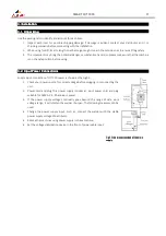
G.
G.
G.
G.
The t
The t
The t
The torch
orch
orch
orch is triggered
is triggered
is triggered
is triggered,,,, but
but
but
but the pilot arc isn’
the pilot arc isn’
the pilot arc isn’
the pilot arc isn’t change to the cut
t change to the cut
t change to the cut
t change to the cutting pilot.
ting pilot.
ting pilot.
ting pilot. The
The
The
The power
power
power
power indicator
indicator
indicator
indicator lights up; Gas
lights up; Gas
lights up; Gas
lights up; Gas
flows; Fan operates
flows; Fan operates
flows; Fan operates
flows; Fan operates....
1.
It is inaccurate connection between torch and power supply, check the torch leads are properly connect to
Summary of Contents for 223001000C
Page 26: ......
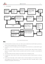
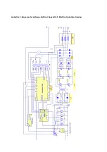
Page 27: ...Apéndice 1 Esquema del sistema eléctrico Appendix 1 Electrical principle drawing ...
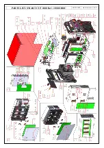
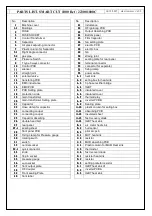
Page 28: ...PARTS LIST SMART CUT 1000 Ref 223001000C 14 12 2015 HR 223001000C V0 1 2 ...
Page 30: ......
Page 31: ......


