background image


SMART CUT 1000


24 


power supply. 

2.


Work  cable  not  connected  to  work  piece,  or  connection  is  poor,  make  sure  that  work  cable  has  a  proper 

connection to a clean and dry area of the workpiece. 

3.


Faulty components in the machine, return for repair or have qualified technician repair per Service Manual. 

4.


Faulty Torch, return for repair or have qualified technician repair it. 

H.

H.

H.

H.


Arc shuts off during operation

Arc shuts off during operation

Arc shuts off during operation

Arc shuts off during operation, and it

, and it

, and it

, and it    will not restart when torch is 

will not restart when torch is 

will not restart when torch is 

will not restart when torch is triggered

triggered

triggered

triggered....    

1.


Power Supply is overheated (OC/OT lamp on), let unit cool down for at least 5 minutes. Make sure the unit has 

not been operated beyond Duty Cycle limit. Refer to Section 2 for duty cycle specifications. 

2.


Gas pressure too low (the TIP/GUN/GAS lamp on when press on torch switch is on), check source for at least 65 

psi / 4.5 bar; adjust as needed. 

3.


Torch consumables worn, check torch shield cup, tip, starter element, and electrode; replace as needed. 

4.


Faulty components in unit:, return for repair or have qualified technician repair per Service Manual. 

5.1.3 Cutting troubles 

D.

D.

D.

D.


No gas flow; the power lamp on; Fan operates

No gas flow; the power lamp on; Fan operates

No gas flow; the power lamp on; Fan operates

No gas flow; the power lamp on; Fan operates    

1.


Gas pipe not connected or pressure is too low, check gas connections. Adjust gas pressure to proper setting. 

2.


Faulty components in the unit, return for repair or have qualified technician repair. 

E.

E.

E.

E.


Low cutting output

Low cutting output

Low cutting output

Low cutting output    

1.


Incorrect setting of cutting current (A), check and adjust to proper setting. 

2.


Faulty components in unit, return for repair or have qualified technician repair. 

F.

F.

F.

F.


Torch 

Torch 

Torch 

Torch can 

can 

can 

can cut but 

cut but 

cut but 

cut but the cutting

the cutting

the cutting

the cutting    quality

quality

quality

quality    is poor

is poor

is poor

is poor    

1.


Current (A) control set too low, increase current setting. 

2.


The torch move too fast across the workpiece, reduce cutting speed. 

3.


Excessive oil or moisture in torch, hold torch 1/8 inch (3 mm) from clean surface while purging and observe oil 

or moisture buildup (do not activate torch). If there are contaminants in the gas, additional filtering may be 

needed. 

4.


Lack of air pressure. Please check the air pressure and air flow, adjust it to the appropriate position 
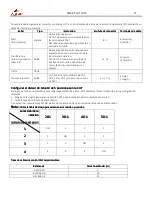


5.2 

Packing and standard accessories

Packing and standard accessories

Packing and standard accessories

Packing and standard accessories


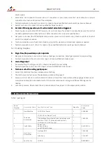
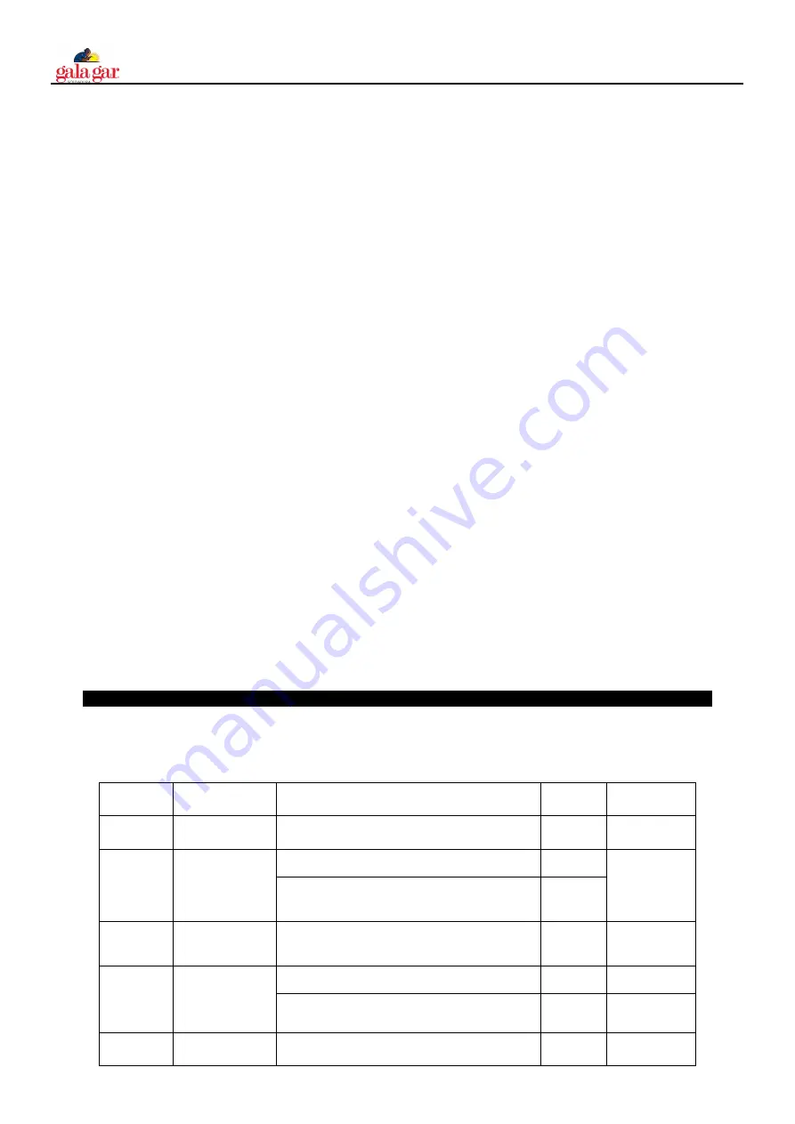
Table 1. packing list 


Serial 
Number  

Accessories Name 


Specification and Type


Quantity  

Accessories 

Code 

Host Machine 

LG-100I Cut Power 

3.008.656 

Torch and 
Accessories 

LT-141 HF Arc Starter Torch 

7.603.224 

One package of nozzle electrode (including nozzle 
aperture 1.4,4;1.7,2;three electrodes; three 

wrenches; one isolating ring)


Earth Cable 

16mm

2

 ,4m 

one quick plug 
one 300A earth clamp 

6.310.322-G 

Gas Circuit 
Accessories 

Gas tube Φ12 

7.501.018 

tube hoop 

7.514.007 

Specification


LG-100 

8.850.660-C 

Summary of Contents for 223001000C

Page 1: ...ROFESIONALES EN BENEFICIO DE SU TRABAJO LEA ATENTAMENTE ESTE MANUAL EN BENEFICIO DE SU TRABAJO LEA ATENTAMENTE ESTE MANUAL EN BENEFICIO DE SU TRABAJO LEA ATENTAMENTE ESTE MANUAL EN BENEFICIO DE SU TRABAJO LEA ATENTAMENTE ESTE MANUAL GB GB GB GB THIS THIS THIS THIS EQUIPM EQUIPM EQUIPM EQUIPMENT MUST BE USED BY PROFESSIONALS ENT MUST BE USED BY PROFESSIONALS ENT MUST BE USED BY PROFESSIONALS ENT MU...

Page 2: ...CA DEL DIVISOR DE TENSIÓN PARA LA SERIE CUT 5 MANTENIMIENTO 12 5 1 GUÍA BÁSICA PARA LA LOCALIZACIÓN DE AVERÍAS 5 2 EMBALAJE Y ACCESORIOS ESTÁNDAR GB GB GB GB CONTENTS CONTENTS CONTENTS CONTENTS Página Página Página Página 1 SAFETY 14 2 TECHNOLOGY PARAMETERS 15 2 1 WORKING PRINCIPLE OF MAIN CIRCUIT 2 2 PARAMETERS 2 3 FEATURES 3 INSTALLATION 17 3 1 UNPACKING 3 2 INPUT POWER CONNECTIONS 3 3 GAS CONNE...

Page 3: ...nformación con relación al tipo y cantidad de humos y gases que pueden ser perjudiciales para su salud Utilice un equipo especial como tablas de corte de agua o de tiro inferior para la captura de los humos y gases En las zonas donde se ubiquen materiales o gases combustibles o explosivos no utilice en ningún caso la antorcha de plasma De los vapores emitidos por los disolventes clorados y los pro...

Page 4: ...guridad deberán medirse periódicamente los niveles de ruido RADIACIONES DEL ARCO DE PLASMA RADIACIONES DEL ARCO DE PLASMA RADIACIONES DEL ARCO DE PLASMA RADIACIONES DEL ARCO DE PLASMA Las radiaciones del arco de plasma pueden ocasionar lesiones en sus ojos y quemaduras en la piel El proceso de corte por arco de plasma produce una luz infrarroja y ultra violeta muy brillante Estas radiaciones del a...

Page 5: ...rriente de corte puede reajustarse de manera continua y progresiva para satisfacer los requisitos de la técnica de corte Fig 2 1 Diagrama del principio de funcionamiento 2 2 2 2 2 2 2 2 PARÁMETROS PARÁMETROS PARÁMETROS PARÁMETROS Tabla 2 1 Parámetros técnicos Modelos Modelos Modelos Modelos Parámetros Parámetros Parámetros Parámetros SMART SMART SMART SMART CUT 1000 CUT 1000 CUT 1000 CUT 1000 Tens...

Page 6: ...ing garantiza a las boquillas y electros El sistema de ignición Back Striking garantiza a las boquillas y electros la velocidad de cebado y la calidad del arco a la vez que prolonga la vida útil de los mismos 3 3 3 3 INSTALACIÓN INSTALACIÓN INSTALACIÓN INSTALACIÓN 3 1 3 1 3 1 3 1 DESEMBALAJE DESEMBALAJE DESEMBALAJE DESEMBALAJE Utilice las listas de embalaje para identificar y da cuentas de cada el...

Page 7: ... corte se utiliza para regular la corriente durante el proceso de corte 4 Alarma de sobretemperatura y sobreintensidad 4 Alarma de sobretemperatura y sobreintensidad 4 Alarma de sobretemperatura y sobreintensidad 4 Alarma de sobretemperatura y sobreintensidad al ser detectadas se enciende un piloto de advertencia 5 Alarma de pistola de corte mal instalada y de baja presión del aire 5 Alarma de pis...

Page 8: ...piloto de la fuente de alimentación se enciende 4 Coloque el interruptor RUN SET en la posición SET para que el aire circule a continuación regular la presión del aire a 3 5 6 0 bar 5 Coloque el interruptor RUN SET en la posición RUN regule la corriente después de que el aire deje de circular 6 En este momento la preparación ha terminado 4 3 Procedimiento de corte Procedimiento de corte Procedimie...

Page 9: ... Durante el periodo de post gas si pulsa el disparador durante un tiempo prolongado el arco se reinicializa si lo pulsa y suelta rápidamente el suministro de gas se corta a continuación puede pulsar el disparador durante un tiempo prolongado para reinicializar también la máquina Encienda la fuente de alimentaci Verificación automática del gas durante 10 segundos Suelte el disparador de la pistola ...

Page 10: ...e circuito abierto Dispone de una salida funcional ELV de muy baja tensión con protección de circuito abierto Dispone de una salida funcional ELV de muy baja tensión con protección de circuito abierto Dispone de una salida funcional ELV de muy baja tensión con protección de circuito abierto Dispone de una salida funcional ELV de muy baja tensión con protección de impedancia para evitar descargas d...

Page 11: ... en la CUT Configurar el divisor de tensión de 5 posiciones en la CUT El divisor de tensión se suministra preconfigurado de fábrica a 20 1 Para cambiar el divisor de tensión a una configuración diferente 1 Ponga el interruptor general en la posición OFF y desconecte el cable de alimentación de red 2 Quite la tapa de la fuente de alimentación 3 Localice los conmutadores DIP del divisor de tensión e...

Page 12: ...ompruebe el flujo de aire alrededor del equipo y resuelva el problema 2 Ventilador bloqueado Compruebe y resuelva el problema 3 La máquina está sobrecalentada Deje que se enfríe durante un periodo de 5 minutos como mínimo Asegúrese de que la máquina no ha funcionado por encima del factor de marcha Consulte el apartado de Parámetros tecnológicos 4 La tensión de entrada supera el rango normal Selecc...

Page 13: ...a na 1 El conducto de alimentación de gas no está conectado o la presión es demasiado baja Compruebe las conexiones de alimentación de gas Regule la presión del gas al valor correcto 2 Hay componentes defectuosos en la máquina Devuélvala para su reparación o que un técnico cualificado la repare B B B B Baja potencia de corte Baja potencia de corte Baja potencia de corte Baja potencia de corte 1 Co...

Page 14: ...als which may contain one or more of the following Antimony Chromium Mercury Beryllium Arsenic Cobalt Nickel Lead Barium Copper Selenium Silver Cadmium Manganese Vanadium Always read the Material Safety Data Sheets MSDS that should be supplied with the material you are using These MSDSs will give you the information regarding the kind and amount of fumes and gases that may be dangerous to your hea...

Page 15: ...g helmet or shield Also always wear safety glasses with side shields goggles or other protective eye wear Wear cutting gloves and suitable clothing to protect your skin from the arc rays and sparks Keep helmet and safety glasses in good condition Replace lenses when cracked chipped or dirty Protect others in the work area from the arc rays Use protective booths screens or shields 2 2 2 2 Technolog...

Page 16: ... FAN Note Note Note Note The above parameters are subject to change with the improvement of machines 2 3 2 3 2 3 2 3 Features Features Features Features 1 IGBT parallel balanced current technology and digital control technology 2 Wider input voltage flexibility provides peak performance power under variable conditions 15 for steady cuts 3 EMI filter restrains the EMI transmission of the power 4 St...

Page 17: ...nections Input Power Connections Supply input connection of CUT100 power is shown as the Fig3 1 1 Check your power source for correct voltage before plugging in or connecting the unit 2 Power Cord and Plug This power supply includes an input power cord and plug suitable for 380V AC 3 Phase input power 3 If the power supply voltage continually goes beyond the range of safe work voltage range it wil...

Page 18: ...proper installation and air pressure low alarm 5 Cutting gun improper installation and air pressure low alarm 6 W 6 W 6 W 6 Work lamp ork lamp ork lamp ork lamp turn on the switch of the cutting gun generate the voltage the lamp on 7 7 7 7 Normal Cut Normal Cut Normal Cut Normal Cut Grid Cut Grid Cut Grid Cut Grid Cut Note When these two functions toggling check gas for 10 seconds and then stop it...

Page 19: ...Normal Cut Normal Cut Normal Cut 1 Normal Cut Fig 4 2 the working flow chart 1 seting time value equal for welding current Turn on the power source Automatic gas test for 10S Loose the cutting torch trigge Pre gas for 1s The torch move away the workpiece then the arc stops Automatic examine for 5s After Initialization and the fan stop press on the torch trigger Ignite the pilot arc the max time is...

Page 20: ...down to 40A in oder to protect the tip 6 Among the period of post gas if you press the trigger for a long time the arc restars if you press and loosen the trigger quickly the gas stops after it you can press the trigger for a long time to restart the machine as well Turn on the power source Loose the cutting torch trigger the arc stops Pre gas for 1s The torch move away the workpiece then the cutt...

Page 21: ...nditions This is an impedance conditions This is an impedance conditions This is an impedance conditions This is an impedance protected functional extra low voltage ELV output to prevent protected functional extra low voltage ELV output to prevent protected functional extra low voltage ELV output to prevent protected functional extra low voltage ELV output to prevent shock energy and fire under no...

Page 22: ... 1 50 1 provides a maximum of 18 V 6 7 6 red 7 black Setting the five Setting the five Setting the five Setting the five position voltage divider on the CUT position voltage divider on the CUT position voltage divider on the CUT position voltage divider on the CUT The factory presets the voltage divider to 20 1 To change the voltage divider to a different setting 1 Turn OFF the power supply and di...

Page 23: ...p lights up lights up after the machine working a few of minutes after the machine working a few of minutes after the machine working a few of minutes after the machine working a few of minutes 1 Air flow blocked check for blocked air flow around the unit and correct condition 2 Fan blocked check and correct condition 3 The machine is over heat let it cool down for at least 5 minutes Make sure the...

Page 24: ...ck gas connections Adjust gas pressure to proper setting 2 Faulty components in the unit return for repair or have qualified technician repair E E E E Low cutting output Low cutting output Low cutting output Low cutting output 1 Incorrect setting of cutting current A check and adjust to proper setting 2 Faulty components in unit return for repair or have qualified technician repair F F F F Torch T...

Page 25: ...IREMENTS OF THE EEC STANDARD DÉCLARA QUE LES PRODUITS PRÉSENTÉS ET RÉFERENCÉS DANS LE MANUEL D INSTRUCTION SONT CONFORMES AUX DIRECTIVES COMMUNAUTAIRES APPLICABLES POUR LE MARQUEE CE PRODUCTO SMART CUT 1000 Ref 223001000C UNEEN60974 1 Equipos de soldadura eléctrica por arco Parte 1 Fuentes de potencia para Soldadura UNEEN60974 10 Equipos de soldadura eléctrica por arco Parte 10 Requisitos de compa...

Page 26: ......

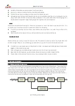
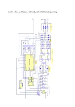
Page 27: ...Apéndice 1 Esquema del sistema eléctrico Appendix 1 Electrical principle drawing ...

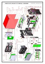
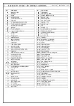
Page 28: ...PARTS LIST SMART CUT 1000 Ref 223001000C 14 12 2015 HR 223001000C V0 1 2 ...

Page 29: ...19 19 19 main transformer A A A A 7 7 7 7 thermal relay 20 20 20 20 main transformer Setting plate A A A A 8 8 8 8 inverter PCB B 21 21 21 21 Capacitor A A A A 9 9 9 9 Sealing plate 22 22 22 22 Hose clamp for capacitor A A A A 10 10 10 10 plastic column for seting box 23 23 23 23 connecting cooper A A A A 11 11 11 11 absorbing PCB 24 24 24 24 connecting cooper A A A A 12 12 12 12 Insulated sheet 2...

Page 30: ......

Page 31: ......

Page 32: ...AL CONSTRUCTIONS FABRICATION ET VENTE D APPAREILS DE SOUDAGE AUTOGÈNE ÉLECTRIQUE ET CONSTRUCTIONS ÉLECTROMÉCANIQUES FABRICO E VENDA DE APARELHAGENS DE SOLDADURA AUTOGÉNEA ELÉCTRICA E CONSTRUÇÕES ELECTROMECÂNICAS CENTRAL Jaime Ferrán 19 nave 30 Apartado de Correos 5058 50080 ZARAGOZA Teléfono 976 47 34 10 Telefax 976 47 24 50 E mail comercial galagar com Internet http www galagar com ...

Reviews: