GALA MIG (V. COMPACTA). Manuel d'Instructions
17
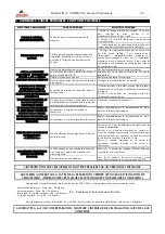
5. ANOMALIES. PROBABLE CAUSES. POSSIBLE SOLUTIONS.
SYMPTOM. ANOMALY.
PROBABLE CAUSE.
POSSIBLE SOLUTION.
1. Make sure there is voltage at the entry to the
machine, if not the tapping must be changed. It is
advisable to see if any magnetothermal has "blown".
2. Check that fuse (E) of the power source is not
open.
GENERAL PROBLEM
NOTHING WORKS.
The machine has no voltage in one or all its
vital elements.
3. The machine panels must be removed testing the
logical points of the electrical diagram.
LIMITER TRIPS
Magnetothermal switch has low gauge for the
case. There may be a short circuit, which is
what causes the limiter to trip.
Change the magnetothermal for another larger
gauge one. It is important for the magnetothermal
switch to have a characteristic slow type curve. It is
important for the magnetothermal switch to have a
characteristic slow type curve. In the event that the
electrical installation has limited power the welding
work must be tested at lower current levels.
Problem in internal connection.
Check that the internal electrical connections are
corrects.
The thermal protection has “blown”. Pilot F
illuminated. (GALA MIG 1810).
Wait until the machine cools down correctly. Do not
disconnect the machine.
Faulty electronic card.
Replace the electronic card.
ALTHOUGH THE MACHINE IS
CONNECTED AND WITH THE
SWITCH ON, THERE IS NO
REACTION WHEN PRESSED
Failure of the pistol switch which does not
make perfect contact.
Change the gun microswitch.
WHEN THE GUN IS PRESSED,
ALTHOUGH WIRE COMES OUT,
THE CONTACTOR DOES NOT
WORK OR/AND THERE IS NO
SHIELDING GAS.
Voltage does not reach the Contactor or/and
solenoid valve.
It must be established whether the fault comes from
the electronic board or if it is an electrical connection
fault.
Check that the contactor coils or/and solenoid valve
are not open.
WHEN THE SHIELDING GAS IS
RELEASED IT CONTINUES
FLOWING.
There is impurity in the inside chamber of the
solenoid valve which prevents the piston from
closing completely.
Dismantle and clean the electrovalve.
WHEN FINISHING WELDING
THE WIRE REMAINS STUCK TO
THE TORCH CONTACT TUBE.
The contactor has a very high opening delay.
Suitably regulate the Burn-Back potentiometer of the
electronic card.
WHEN FINISHING WELDING
THE FINAL WIRE LENGTH IS
VERY GREAT.
The contactor has a very low opening delay.
Suitably regulate the Burn-Back potentiometer of the
electronic card.
THE EQUIPMENT DOES NOT
WELD CORRECT.
"IT ADJUSTS BADLY"
Low effective welding voltage. Output wave not
correct.
Check that there is not a phase failure in the supply
power.
Check that the electrical contact elements of the
welding circuit are correct: Welding mass, rusty or
very dirty surfaces, contact nozzle with greater
diameter than the wire, etc.
Test the electrical diagram of the power source: input
and output voltages to the rectifier.
The welding wire has a mechanical resistance
at the outlet, which prevents it from having a
regular speed.
Examine the welding gun. Blow the inside (cable)
with compressed air.
THERE ARE MANY
PROJECTIONS IN THE WELDING
PROCESS
Unsuitable shielding gas.
When welding normal steels we advise the use of a
gas mixture Ar-CO2.
SPECIALIZED PERSONNEL MUST CARRY OUT ANY WORK ON THE EQUIPMENT.
BOTH AT THE BEGINNING AND END OF A REPAIR CHECK THE EQUIPMENT INSULATION LEVELS.
(DISCONNECT THE ELECTRONIC CARDS WHEN MEASURING THE INSULATION).
The insulation-measuring device will have 500 V DC and will be applied to the following points of the circuit:
- Intake rectifier-Earth: Ra> 50 Mohms
- Outlet rectifier-Earth: Ra> 50 Mohms
- Switch l2 - Outlet rectifier: Ra> 50 Mohms
- Control circuit-Earth: Ra> 50 Mohms
Ra: Insulation resistance in Mohms.
In the event that lack of insulation is observed it is likely that this is due to the accumulation of metal dust on the
inside of the equipment.
BOTH AT THE BEGINNING AND END OF A REPAIR, BLOW THE INSIDE OF THE EQUIPMENT WITH
COMPRESSED AIR.
Summary of Contents for 53100000
Page 39: ......


