


GALA G.E. TIG PULSE
15
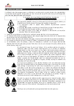
2. TRANSPORT AND INSTALLATION.
2.1. TRANSPORT AND PACKAGING.
Knocks and sudden movements must be avoided when transporting the equipment. In any case, the packaging
must be protected from water.
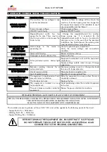
HANDLE THE EQUIPMENT CAREFULLY, IT WILL LAST LONGER !
2.2. ELECTRICAL SUPPLY INSTALLATION.
ELECTRICAL INSTALLATIONS SHOULD ONLY BE HANDLED BY SPECIALISED PERSONNEL.
The location must fulfill the following conditions:
-
Place: Dry and ventilated. Far enough away from the welding area in order to prevent the dust caused by the
welding process from getting into the equipment. Never work in the rain.
-
The distribution panel where the machine has to be connected must have the following elements, at least:
DIFFERENTIAL SWITCH (ID): Bi-polar or Tri-polar with a minimum sensitivity of 300 mA. The aim of this switch is
to protect the personnel from direct or indirect contact with electrical parts under voltage.
AUTOMATIC CIRCUIT BREAKER (IA): Bi-polar. A 32 A IA is recommended.
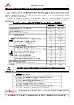
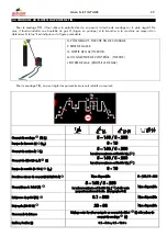
IMPORTANT! Verify that the wire is connected to a plug with an efficient earth tap. The plug must be adequate
for at least 25 A. If a longer supply hose or connection to an extension must be used, bear in mind the values of this
table.
GALA G.E. TIG PULSE
Length
CROSS-SECTION
Up to 150m
4 mm
2
> 15 m Up to 50 m
6 mm
2
These values are for reference and are influenced
by the state of the conductors, connections and
ambient temperature.
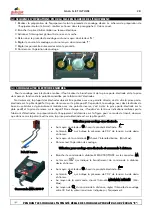
BEFORE STARTING THE EQUIPMENT, VERIFY THAT THE ELECTRODE TONG IS
SEPARATED FROM THE WELDING MASS.
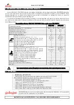
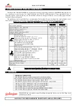
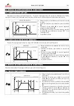
2.3. ELECTRICAL INSTALLATION TO ELECTRICAL GENERATING SET.
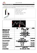
GALA G.E. appliances are suitable for electrical installation to electrical generating set. This equipment includes a
protection system, which continuously verifies the supply voltage, so that, as soon as this voltage is outside the
margins admitted (between 196 V and 265 V), or it is dangerously distorted, the equipment will be protected,
isolating the sensitive circuits from the mains. Under these conditions, the equipment will remain switched off or the
amber coloured indicator, “E”, will light up (see section 3). When the voltage is suitable again, the appliance will be
ready to operate.
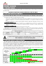
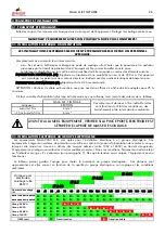
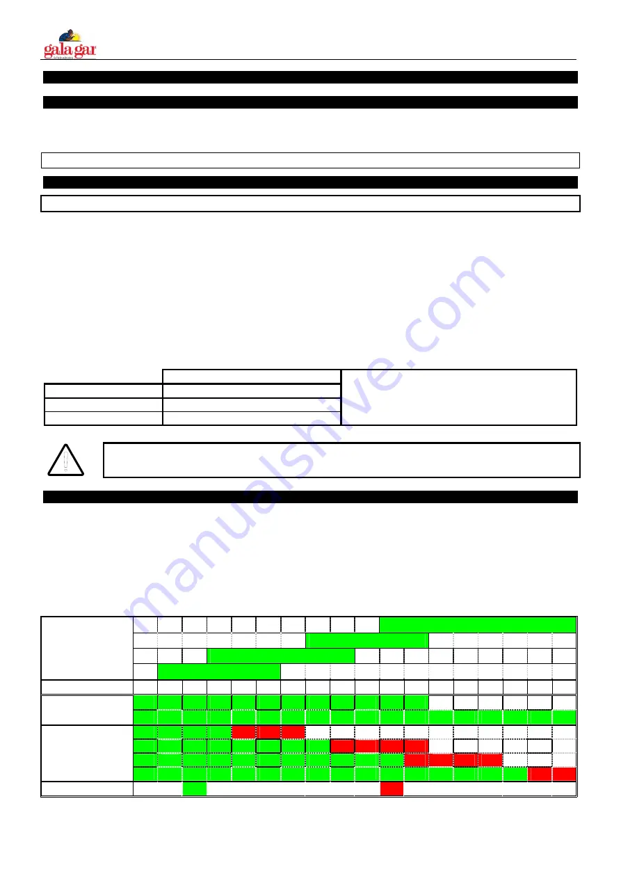
The table below will help you choose the power of the generating set. These data are approximate and vary with
the quality of the generating set, its adjustment and environmental conditions.
Ø 4.00
Ø 3.25
Ø 2.5
Data for rutile
electrode E6013
Ø 2.00
Welding current (A)
30 40 50 60 70 80 90 100 110 120 130 140 150 160 170 180 190 200
GALA 1700 GE TIG PULSE
►
►
►
►
►
►
►
►
►
►
►
►
GALA 2000 GE TIG PULSE
►
►
►
►
►
►
►
►
►
►
►
►
►
►
►
►
►
►
2.5 KVA set
►
►
►
►
◙
◙
◙
4 KVA set
►
►
►
►
►
►
►
►
◙
◙
◙
◙
5.5 KVA set
►
►
►
►
►
►
►
►
►
►
►
◙
◙
◙
◙
10 KVA set
►
►
►
►
►
►
►
►
►
►
►
►
►
►
►
►
◙
◙
(300 rpm)
►
Continuous work
◙
Possible work


