Page
5
of
5
11.
Connect the reader wiring to the DRM board:
•
6-conductor, 22 AWG, overall shielded; max cable distance is 500 feet to the panel.
•
Ground the Drain-wire at one end only - at the DRM Board (GND).
•
Reader will require separate power supply if the current draw is over 150 mA
•
Refer to manufacturer’s instructions for wiring (manufacturer's specs may supersede Galaxy specs).
Wiegand Reader
635-DRM Terminals (Function)
LED Control
LED
(LED control line)
DATA 1
D 1
(Data 1)
VDC
VDC
(+12 VDC)
*for +5VDC use Regulator PN 92-3001-05
GND
GND
(Power Supply Ground)
DATA 0
D 0
(Data 0)
See System Galaxy Online Help
for additional reader formats.
12.
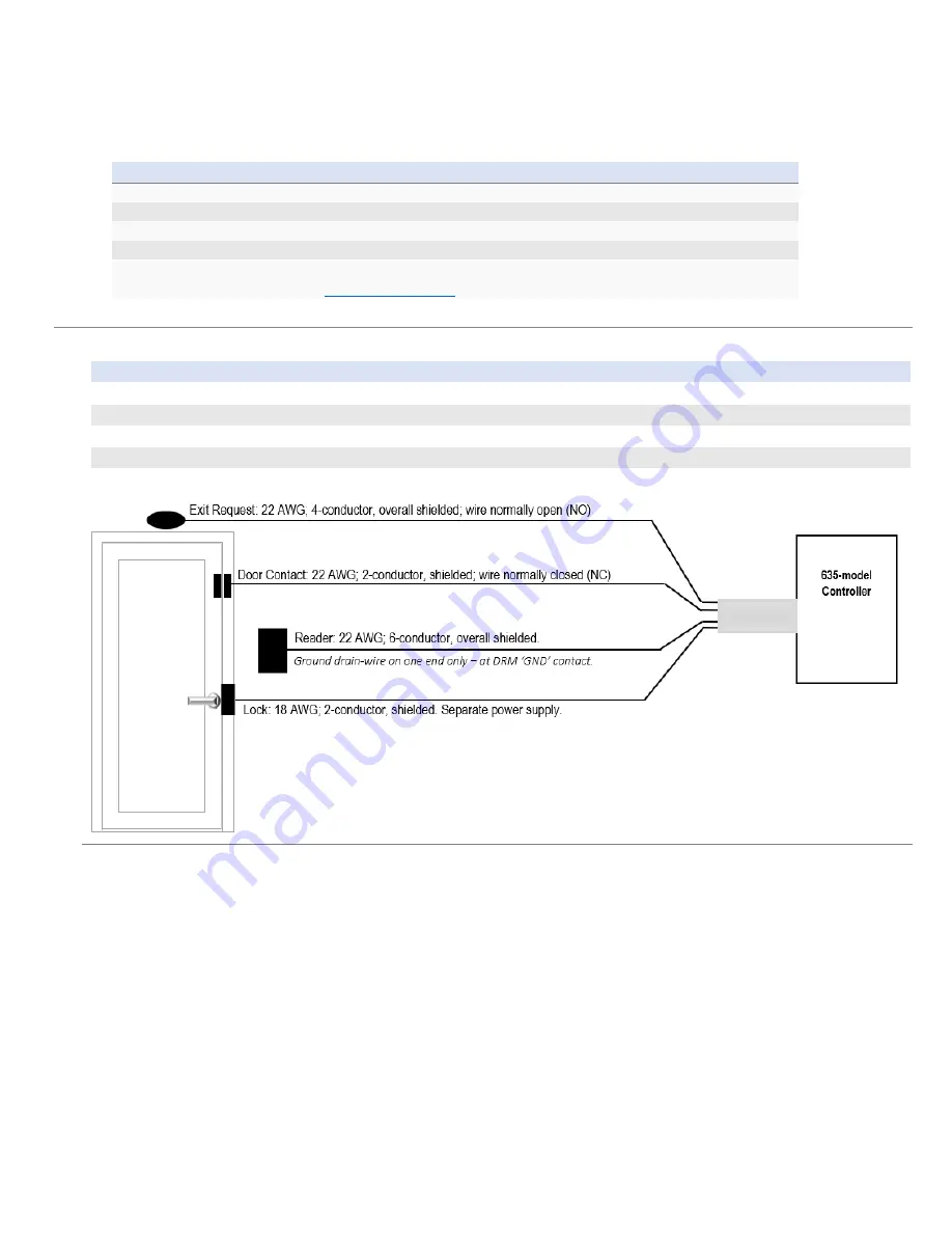
Connect the Lock, Door Contacts, and REX to the DRM …
Connection Type Max Distance
Wire Gauge & Specifications
Request to Exit
500 ft. from controller
22 AWG; 4-conductor, overall shielded; wired normally open (NO)
Door Contact
500 ft. from controller
22 AWG; 2-conductor, overall shielded; wired normally closed (NC)
Lock Hardware
500 ft. from controller
18 AWG; 2-conductor minimum, shielded; Separate Power Supply.
Refer to manufacturer’s instructions for device wiring (manufacturer's specs may supersede Galaxy specs).
13.
Jumper-out unused contacts, as follows
a)
DRM board: If
Door Contacts
are not installed, you must jumper-out CNT to GND.
b)
CPU board: If
Low Battery
wiring is not installed, you must jumper-out Low Batt to GND.
c)
CPU board: If
AC Fail
wiring is not installed, you must jumper-out the AC Fail to GND.
14.
Now you are ready to add your
Cluster
and
Controller
information into the SG software programming screens.
•
The software can auto-import the daughter boards into the Controller programming screen by clicking the
[Get Boards] button, as long as they are physically attached to the CPU I2C-Data (ribbon cable).
•
You must manually program each Reader, Input, and Output into the SG programming screens and make
any schedules you need.
15.
Test that your Tamper Switch is working is working on each controller. The CPU reports
tamper events
to System
Galaxy software.


