- 3 -
DX 949
CHAPTER 2
OPERATION
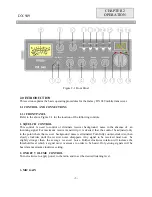
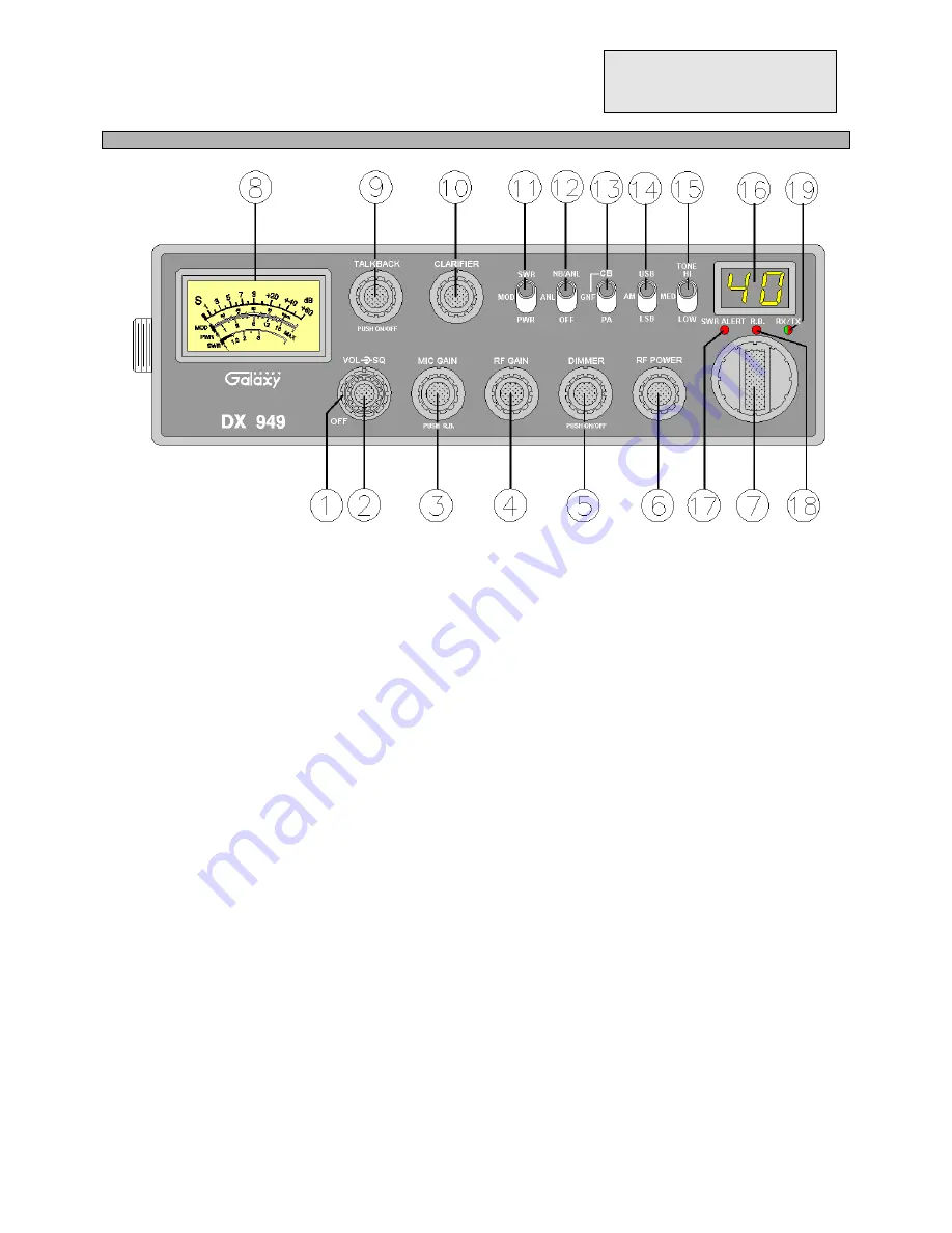
Figure 2-1 Front Panel
2.0 INTRODUCTION
This section explains the basic operating procedures for the Galaxy DX 949 mobile transceiver.
2.1 CONTROL AND CONNECTIONS
2.1.1 FRONT PANEL
Refer to the above Figure 2-1 for the location of the following controls.
1. SQUELCH CONTROL
This control is used to control or eliminate receiver background noise in the absence of an
incoming signal. For maximum receiver sensitivity, it is desired that the control be adjusted only
to the point where the receiver background noise is eliminated. Turn fully counter-clockwise, then
slowly clockwise until the receiver noise disappears. Any signal to be received must now be
slightly stronger than the average received noise. Further clockwise rotation will increase the
threshold level which a signal must overcome in order to be heard. Only strong signals will be
heard at a maximum clockwise setting.
2. ON/OFF VOLUME CONTROL
Turn clockwise to apply power to the radio and to set the desired listening level.
3. MIC GAIN
Summary of Contents for DX 949
Page 1: ......
Page 13: ...12 DX 949 CIRCUIT DIAGRAM...
Page 14: ...13 CHAPTER 4...
Page 18: ...17 Figure 4 2 Receiver test setup...
Page 19: ...18 Figure 4 3 Main PCB Adjustment Locations CHAPTER 5...
Page 23: ...22...
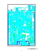
Page 29: ...28 DX 949 MAIN PCB REMARK SOLDER SIDE WHITE...
Page 33: ...32...
Page 34: ...33 AT0949040A...
Page 35: ...34...


