- 5 -
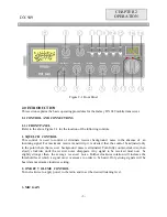
In the PA position, your voice will come out of the speaker that you need to plug in to the PA. SP.
jack on the rear panel. The radio does not operate when you are in the PA mode. The CB mode is
normal operation of the radio. In the GNF mode, you are in CB operation but the Galaxy Noise
Filter is engaged. This is a special noise filter that de-emphasizes audio high frequency response in
order to increase the signal-to-noise ratio of weak signals. While you will notice a dramatic
reduction in the “rushing” sound when this filter is activated, it does not have much effect on the
signal-to-noise ratio of strong signals. It is mostly used for SSB reception.
14. MODE SWITCH
This control allows you to select one of the following operating modes : USB/AM/LSB .
15. TONE SWITCH HI/MED/LO
This switch changes tone quality in receive only. In LO position, bass is increased and in HI
position, treble is increased.
16. CHANNEL DISPLAY
The channel display indicates the current selected channel.
17. SWR ALERT LED
This LED lights red when your SWR is higher than about 3:1. This is not an exact indicator of 3:1
SWR, but it is an indication that you should check your SWR reading.
18. R.B. LED
This lights green when the Roger Beep is on.
19. RX/TX LED
This LED lights green during receive and red during transmit.
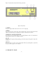
2.1.2 REAR PANEL
Summary of Contents for DX 949
Page 1: ......
Page 13: ...12 DX 949 CIRCUIT DIAGRAM...
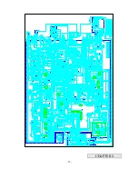
Page 14: ...13 CHAPTER 4...
Page 18: ...17 Figure 4 2 Receiver test setup...
Page 19: ...18 Figure 4 3 Main PCB Adjustment Locations CHAPTER 5...
Page 23: ...22...
Page 29: ...28 DX 949 MAIN PCB REMARK SOLDER SIDE WHITE...
Page 33: ...32...
Page 34: ...33 AT0949040A...
Page 35: ...34...


