- 6 -
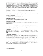
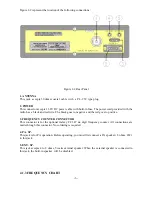
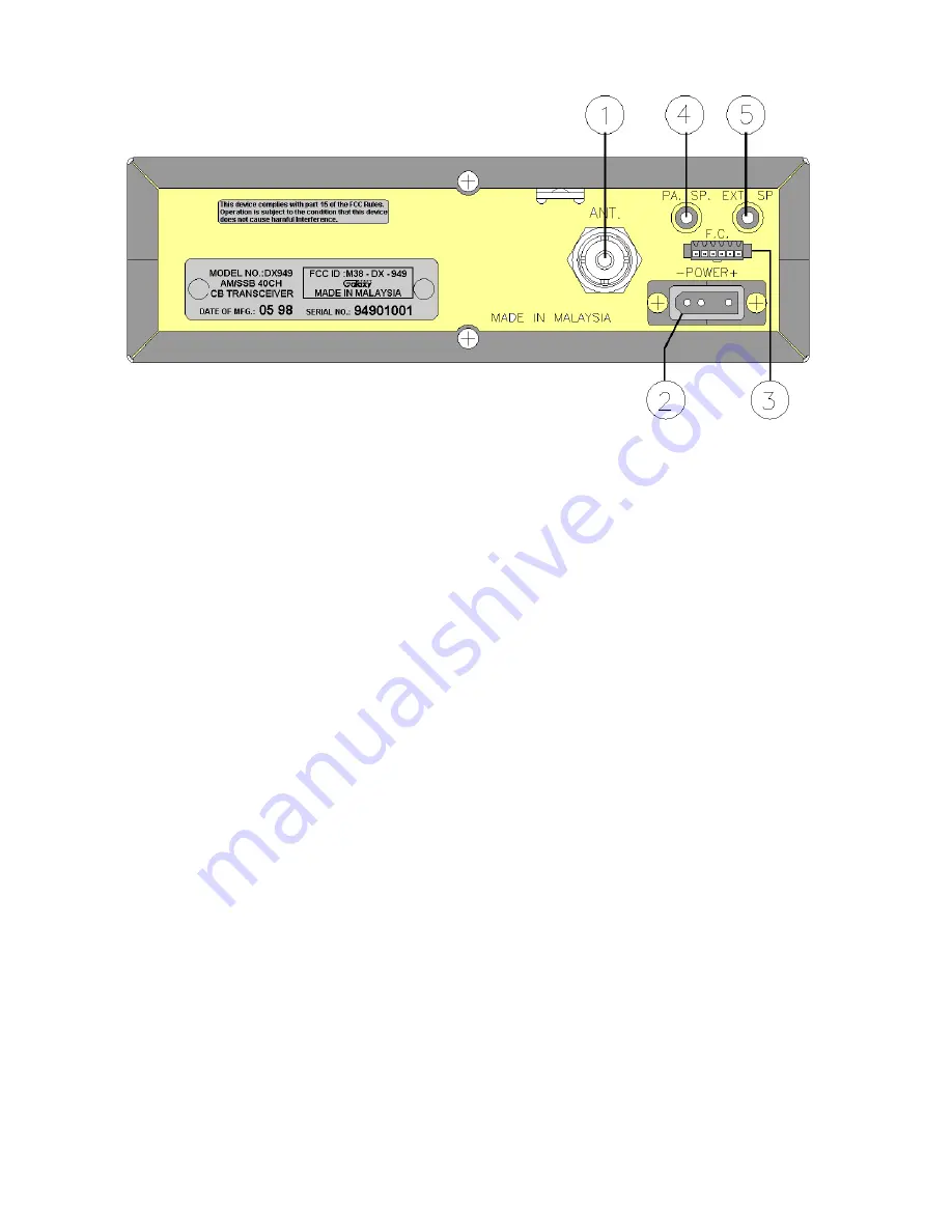
Figure 2-2 represent the location of the following connections :
Figure 2-2 Rear Panel
1. ANTENNA
This jack accepts 50 ohms coaxial cable with a PL- 259 type plug.
2. POWER
This connector accepts 13.8V DC power cable with built-in fuse. The power cord provided with the
radio has a black and red wire. The black goes to negative and the red goes to positive.
3. FREQUENCY COUNTER CONNECTOR
This connector is for the optional Galaxy FC 347 six digit frequency counter. All connections are
made through this connector. No soldering is required.
4. PA. SP.
This jack is for PA operation. Before operating, you must first connect a PA speaker ( 8 ohms, 4W )
to this jack.
5. EXT. SP.
This jack accepts 4 to 8 ohms, 5 watts external speaker. When the external speaker is connected to
this jack, the built-in speaker will be disabled.
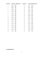
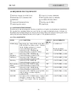
2.1.3 FREQUENCY CHART
Summary of Contents for DX 949
Page 1: ......
Page 13: ...12 DX 949 CIRCUIT DIAGRAM...
Page 14: ...13 CHAPTER 4...
Page 18: ...17 Figure 4 2 Receiver test setup...
Page 19: ...18 Figure 4 3 Main PCB Adjustment Locations CHAPTER 5...
Page 23: ...22...
Page 29: ...28 DX 949 MAIN PCB REMARK SOLDER SIDE WHITE...
Page 33: ...32...
Page 34: ...33 AT0949040A...
Page 35: ...34...


