
Galaxy GHDXS2-1430R-16F4D Installation and Hardware Reference Manual
1-4
Major Subsystem Components
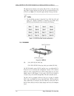
Once the subsystem is rebooted, all system configurations revert to the
default stage so that
Controller A
becomes the primary controller and
Controller B
the secondary controller.
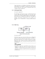
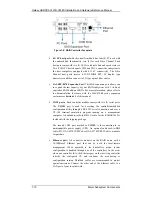
BBUs:
Two (2) BBUs come as standard equipment for the dual-
controller GHDX2-1430R-16F4D. Each BBU sustains cache
memory for days during a power outage to prevent data loss. These
BBUs are hot-swappable. (See
Section 1.3.5.
)
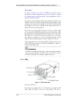
PSUs:
The hot-swappable, load-sharing PSUs convert 110V or
240V input to 3.3V, 5V, or 12V for subsystem components.
Subsystem power-on/off is controlled by a power switch on each
PSU. (See
Section 1.3.6.
) These modules contain the subsystem’s
cooling modules. The redundant cooling modules ventilate the
chassis with an airflow traveling from the front to the rear. (See
Section 1.3.7.
)
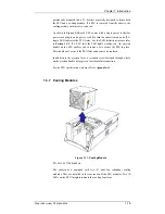
1.2.3 Integrated Backplane
An integrated backplane board separates the front and rear sections of the
chassis. This circuit board provides logic level signals and low voltage
power paths. Thermal sensors and I
2
C devices are implemented to detect
system temperature and PSU/cooling module presence signals. This board
contains no user-serviceable components.
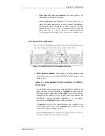
The backplane board is designed for dual-ported SAS drives. Every disk
drive is connected through two separate SAS domains and each SAS
domain is individually managed by a RAID controller in a dual-controller
configuration.
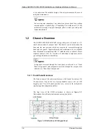
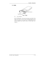
1.2.4 Physical Dimensions
The RAID subsystem comes in an enhanced 3U chassis with the following
dimensions:
With handles: 488.6mm (W) x 131mm (H) x 504.3mm (L) (19 x
5.2 x 21 inches)
Without handles: 445mm x 130mm x 488.2mm (17.5 x 5.1 x 19.2
inches)
1.3
Major Subsystem Components
Both RAID models house many active components and most of them can
be accessed through either the front or rear panel. The modular enclosure


