
Chapter 1: Introduction
Major Subsystem
Components
1-15
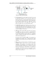
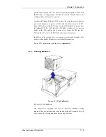
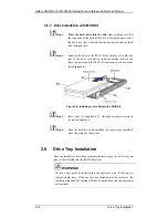
permanently mounted into a 2U bracket especially designed to house both
the PSU and a cooling module. If a PSU is removed from the chassis, the
cooling module within is also removed.
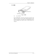
As shown in
Figure 1-10
, each PSU comes with a single power socket for
power cord plug-in and a power switch to turn the subsystem on and off. A
single LED indicates the PSU status. For the LED definitions, please refer
to
Section 4.4.9
. If a PSU fails the LED lights steadily red. An ejection
handle on the PSU enables you to remove or to secure the PSU in place.
This should only occur if the PSU fails and needs to be replaced.
In addition to the ejection lever, a retention screw fastened through a hole
on the ejection handle helps prevent accidental disconnection.
For the PSU specifications, please refer to
Appendix A.4
.
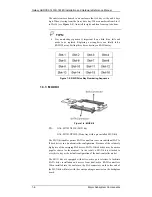
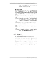
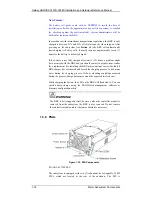
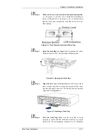
1.3.7 Cooling
Modules
Figure 1-11: Cooling Module
PN: GAL-9273ECFanMod
The subsystem is equipped with two (2), dual-fan, redundant cooling
modules. They are installed in the rear section of the PSU modules. Two (2)
LEDs on the PSU faceplate indicate the cooling fan status.


