Chapter 2: Hardware Installation
BBU Installation
2-13
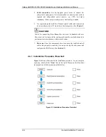
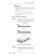
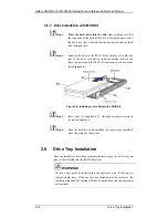
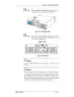
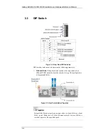
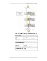
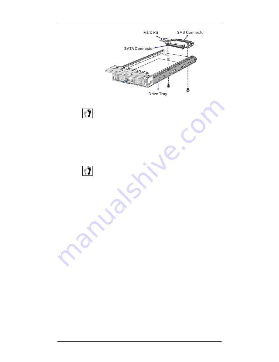
Figure 2-10: Installing a MUX Kit
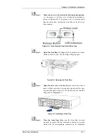
Step 1.
Orient the MUX kit with mounting positions near the open
end of the drive tray. The SATA connector should face the
front side and the SAS connector should face the rear side.
Align the mounting holes on the drive tray with those on the
MUX kit.
The SAS and SATA interfaces look similar. A SAS connector
has pins on both sides.
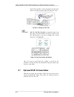
Step 2.
Secure the MUX kit by driving the included two (2) retention
screws from the bottom of the drive tray. (See
Figure 2-10
)
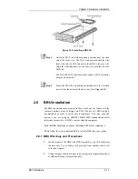
2.8 BBU
Installation
The BBU can sustain cache memory in the event of a power failure or in the
extremely unlikely event of failing both PSUs. The use of a BBU is highly
recommended in order to avoid data inconsistency. You may skip this
section if you are using an GHDX2-1430R-16F4D redundant-controller
subsystem because two (2) BBUs come as standard equipment.
Read the BBU handling precautions in
Section 2.8.1
before replacing it.
Please follow the steps in
Section 2.8.2
to install a BBU into your system.
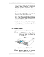
2.8.1 BBU Warnings and Precautions
Install or replace the BBU with BBUs supplied by your ES subsystem
vendors only. Use of battery cells provided from another source will
void your warranty.
Always dispose of used batteries in an ecologically responsible manner
at authorized battery disposal sites only.


