Chapter 4: Subsystem Operation and Monitoring
Power On
4-3
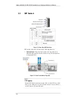
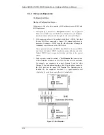
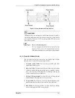
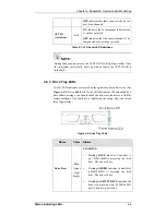
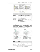
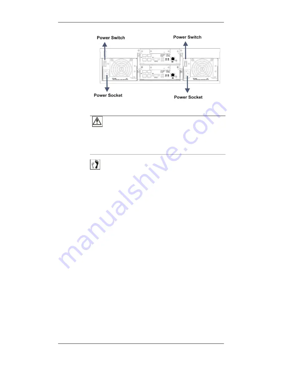
Figure 4-1: Power Sockets and Power Switches
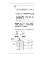
CAUTION!
Although the PSUs are configured in a fault-tolerant pair and a single PSU
can provide sufficient power to the system, it is necessary to turn on both
power supplies. If only one (1) PSU is operating and that PSU fails, system
down time will occur.
Step 4.
Power on the host computers.
The host computers should be the last devices that are
turned on. Please refer to the documentation that came
with your host computers to see their power on procedures.
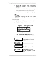
4.1.3 Power On Status Check
Once the subsystem has been powered on, you should begin verifying
subsystem status via the following monitoring interfaces:
1.
Controller module LEDs:
The Ctlr_Status and BBU_Link LEDs
should light constantly green.
2.
Drive tray LEDs:
The blue status LEDs on all drive trays that contain
a hard drive should light up showing that power is supplied to the disk
drives. The Drive Busy LEDs should also start flashing, indicating that
system is attempting to access hard drives.
3.
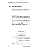
LEDs on LCD keypad panel:
The blue LED on the LCD keypad panel
should illuminate, indicating that system status is ready.
4.
FC port LEDs:
The LED below each FC port should illuminate green,
indicating that the Fibre Channel connection has been established.
5.
BBU LEDs:
The LEDs on the BBU rear panel should start flashing
amber, indicating that the BBU is being charged.


