Galaxy GHDXS2-1430R-16F4D Installation and Hardware Reference Manual
4-8
Status-indicating
LEDs
4.4 Status-indicating
LEDs
4.4.1 Brief Overview of the LEDs
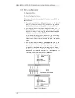
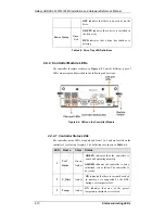
All FRUs (Field Replaceable Units) have status-indicating LEDs that reflect
the operational status and integrity of the subsystem components. The list in
Error! Reference source not found.
shows the number of LEDs that reside
on each component.
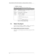
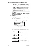
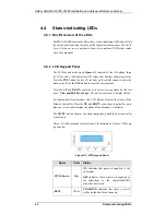
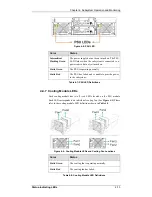
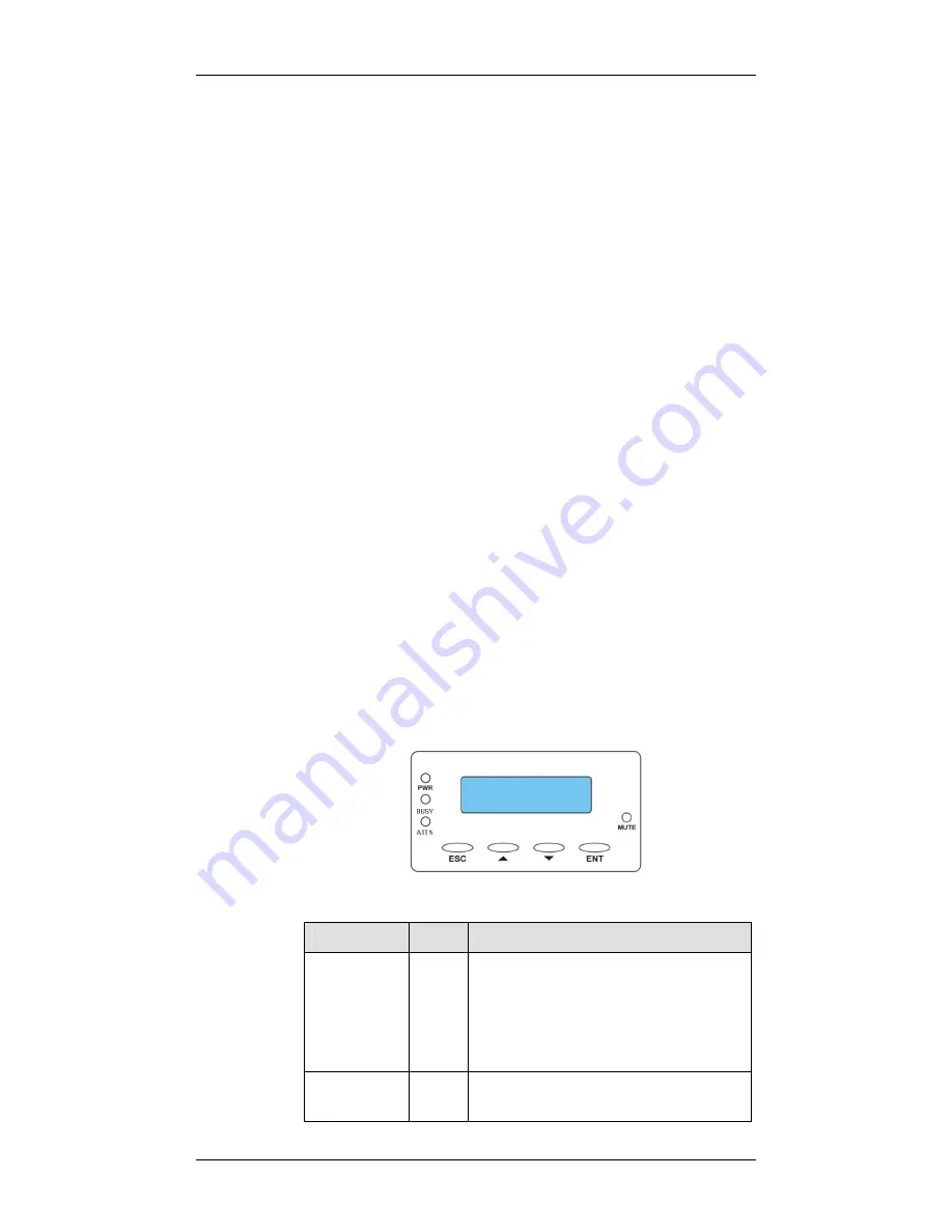
4.4.2 LCD Keypad Panel
The LCD keypad as shown in
Figure 4-3
consists of five (5) buttons, three
(3) LEDs, and a 16x2-character LCD screen that displays subsystem status.
Press the
ENT
button for two (2) seconds on the initial screen to enter the
main menu. Press the
ESC
button to clear the current event.
Press the
UP
and
DOWN
arrow keys to select viewing items. In the last
item, “
View and Edit Event Logs
,” the most recent event is displayed first.
For dual-controller subsystems, the LCD always displays the status of the
Primary Controller. Press the
UP
and
DOWN
arrow keys together for more
than one (1) second to display the status of the Secondary Controller.
The
MUTE
button silences the alarm temporarily until the next controller
event occurs.
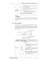
Three (3) LEDs monitor system status. The definitions of these LEDs are
given below.
Figure 4-3: LCD Keypad Panel
Name
Color
Status
PWR (Power)
Blue
ON
indicates that power is supplied to the
subsystem.
OFF
indicates that no power is supplied to
the subsystem or the subsystem/RAID
controller has failed.
BUSY
White
FLASHING
indicates that there is active
traffic on the host/drive channels.


