
Chapter 4: Subsystem Operation and Monitoring
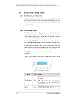
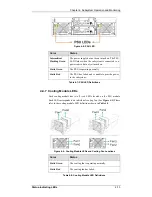
Status-indicating LEDs
4-11
4
BBU
Link
Green
ON
indicates BBU is present.
5 Hst
Bsy
Green
FLASHING
indicates there is
active
traffic through the host ports.
OFF
indicates there is no activity on the
host ports.
6 Drv
Bsy
Green
FLASHING
indicates there is
active
traffic on the drive channels.
OFF
indicates there is no activity on the
drive channels.
Table 4-3: Controller Status LED Definitions
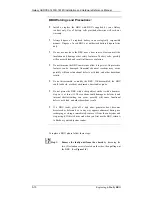
4.4.4.2 Fibre
Port
LEDs
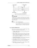
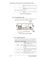
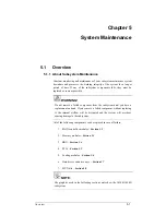
Each controller module houses four (4) 4G FC host ports. Each of these
Fibre ports has two (2) LEDs (see
Figure 4-5
) for displaying the operating
statuses.
1 Link
Green
ON
indicates there the FC port is
connected to a FC node or networking
device.
OFF
indicates no valid link.
2 Speed
Green/
Amber
GREEN
indicates link speed at 4Gbps.
AMBER
indicates link speed at 2Gbps.
OFF
indicates link speed at 1Gbps or other
conditions.
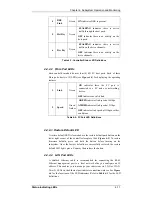
Table 4-4: FC Port LED Definitions
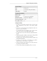
4.4.4.3 Restore Default LED
A restore default LED is located above the restore default push button on the
lower right corner of the controller faceplate. (See
Figure 4-5
) To restore
firmware defaults, press and hold the button before turning on the
subsystem. Once the factory defaults are successfully restored, the restore
default LED lights green. You may then release the button.
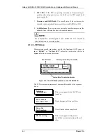
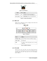
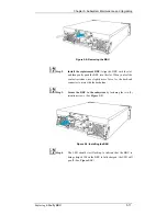
4.4.4.4 LAN Port LEDs
A shielded Ethernet cable is recommended for connecting the RJ-45
Ethernet management port to a local network after you configure an IP
address. This enables you to manage your subsystem via LAN or WAN.
Two (2) LEDs on the Ethernet port indicate connection statuses. See
Figure
4-6
for the locations of the LED indicators. Refer to
Table 4-5
for the LED
definitions.


