background image

TABLE OF CONTENTS

12

THE MACHINE AND ITS OPERATIONS

3.1

MACHINE ILLUSTRATIONS ................................................................................................................

58

3.1.1

OVERALL VIEW OF THE MACHINE .......................................................................................

58

3.1.2

CONTROLS AND GAUGES.....................................................................................................

59

3.2

INSTRUMENTS AND CONTROLS .......................................................................................................

60

3.2.1

WARNING LIGHTS AND GAUGES .........................................................................................

60

3.2.1.1

EMERGENCY WARNING LIGHTS.........................................................................

61

3.2.1.2

GAUGES .................................................................................................................

62

3.2.1.3

WARNING LIGHTS .................................................................................................

63

3.2.2

SWITCHES AND PUSH BUTTONS .........................................................................................

65

3.2.3

CONTROL LEVERS AND PEDALS .........................................................................................

68

3.2.4

COVERSWITH LOCK...............................................................................................................

75

3.2.5

ENGINE HOOD ........................................................................................................................

76

3.2.6

RADIATOR COVER .................................................................................................................

77

3.2.7

BATTERY COVER ...................................................................................................................

78

3.2.8

TILTING THE CAB FLOOR ......................................................................................................

79

3.2.9

FUSES......................................................................................................................................

82

3.2.10 MAIN FUSE ..............................................................................................................................

83

3.2.11 TECHNICAL DOCUMENTATION COMPARTMENT ...............................................................

83

3.2.12 TOOL BOX ...............................................................................................................................

83

3.3

USE OF THE MACHINE AND RELATED CONTROLS........................................................................

84

3.3.1

BEFORE STARTING THE ENGINE.........................................................................................

84

3.3.1.1

VISUAL CHECKS....................................................................................................

84

3.3.1.2

CHECKS TO BE CARRIED OUT BEFORE STARTING THE ENGINE ..................

85

3.3.1.3

ADJUSTMENTS......................................................................................................

92

3.3.1.4

OPERATIONS TO BE CARRIED OUT BEFORE STARTING THE ENGINE .........

94

3.3.2

STARTING THE ENGINE.........................................................................................................

96

3.3.2.1

STARTING WITH WARM ENGINE OR IN WARM CLIMATES...............................

96

3.3.2.2

STARTING WITH COLD ENGINE OR IN COLD CLIMATES .................................

98

3.3.3

AFTER STARTING THE ENGINE............................................................................................

100

3.3.3.1

RUNNING IN A NEW MACHINE.............................................................................

100

3.3.3.2

WARMING-UP OPERATIONS................................................................................

101

3.3.4

STOPPING THE ENGINE ........................................................................................................

103

3.3.5

HOW TO MOVE THE MACHINE..............................................................................................

104

3.3.5.1

PRELIMINARY OPERATIONS TO BE CARRIED OUT BEFORE 
MOVING THE MACHINE ........................................................................................

104

3.3.5.2

MOVING THE MACHINE FORWARD ....................................................................

104

3.3.5.3

MOVING THE MACHINE IN REVERSE .................................................................

106

3.3.5.4

STOPPING THE MACHINE ....................................................................................

107

3.3.6

STEERING THE MACHINE......................................................................................................

108

3.3.6.1

STEERING (CHANGING DIRECTION) ..................................................................

108

3.3.7

SWINGING THE TURRET .......................................................................................................

110

3.3.8

WORK EQUIPMENT CONTROLS AND FUNCTIONS.............................................................

111

3.3.9

UNAUTHORIZED OPERATIONS.............................................................................................

114

3.3.10 PRECAUTIONS FOR USE.......................................................................................................

116

3.3.11 PRECAUTIONS TO BE TAKEN WHEN TRAVELLING ON SLOPES......................................

118

3.3.12 GETTING THE MACHINE OUT OF MUD ................................................................................

120

3.3.13 OPERATIONS THAT CAN BE PERFORMED WITH THE HYDRAULIC EXCAVATOR ..........

121

3.3.14 CHANGING THE BUCKET.......................................................................................................

123

3.3.15 PARKING THE MACHINE........................................................................................................

124

3.3.16 CHECKING THE MACHINE EVERY DAY AFTER WORK ......................................................

126

3.3.16.1

BEFORE STOPPING THE ENGINE .......................................................................

126

3.3.16.2

AFTER STOPPING THE ENGINE ..........................................................................

126

Summary of Contents for PC16R-2

Page 1: ...s and maintenance personnel must read this manual before operating or maintaining this machine This manual should be kept inside the cab for reference and periodically reviewed by all personnel who wi...

Page 2: ......

Page 3: ...nce operations that have been carried out are important since they provide a clear report on the situation and say exactly what has been done and what has to be done after the next maintenance interva...

Page 4: ...of this term must be limited to situations of extreme danger WARNING q Indicates a situation of potential danger that if not avoided may cause serious injury and even death CAUTION q Indicates a situ...

Page 5: ...WARNING q It is strictly forbidden to modify the setting of the hydraulic system safety valves Komatsu cannot be held liable for any damage to persons property or the machine if this has been tampere...

Page 6: ...lings necessary for the operation of such equipment are grouped in the final section of this manual Komatsu machines are constructed exclusively for the handling excavation and treatment of inert mate...

Page 7: ...and abrupt reversals SYNTHETIC BIODEGRADABLE OIL TYPE HEES For machines in which synthetic biodegradable oil type HEES is used perform the following operations in addition to the standard maintenance...

Page 8: ...N PLATE AND PRODUCT IDENTIFICATION NUMBER PIN The Komatsu excavators described in this manual are CE marked in fact they are in compliance with the EU harmonised standards The plate with the CE markin...

Page 9: ...amped on the plate positioned on the engine itself The exhaust gas emission plate is applied to the counterweight 1 4 4 TRAVEL REDUCTION GEAR SERIAL NUMBER The serial number is stamped on the plate po...

Page 10: ...PRODUCT IDENTIFICATION 8 1 4 5 SWING REDUCTION GEAR SERIAL NUMBER The serial number is stamped on the plate positioned on the upper side of the swing motor RKAB5920...

Page 11: ...IDENTIFICATION 9 1 4 6 SERIAL NUMBERS AND DEALER S ADDRESS Machine no Model Product identification number PIN Travel reduction gear no Swing reduction gear no Dealer Address Tel Contact person NOTES E...

Page 12: ...1 4 VIBRATIONS TO WHICH THE OPERATOR IS SUBJECTED 24 2 2 GENERAL PRECAUTIONS 25 2 2 1 GENERAL SAFETY RULES 25 2 2 2 SAFETY DEVICES AND GUARDS 25 2 2 3 CLOTHING AND PERSONAL PROTECTION ITEMS 25 2 2 4 U...

Page 13: ...8 7 USE OF THE ENGINE DURING MAINTENANCE 50 2 8 8 PERIODICAL CHANGE OF THE PARTS THAT ARE CRITICAL FOR SAFETY 50 2 8 9 STOP THE ENGINE BEFORE CARRYING OUT ANY MAINTENANCE OPERATION OR INSPECTION 50 2...

Page 14: ...GINE 96 3 3 2 1 STARTING WITH WARM ENGINE OR IN WARM CLIMATES 96 3 3 2 2 STARTING WITH COLD ENGINE OR IN COLD CLIMATES 98 3 3 3 AFTER STARTING THE ENGINE 100 3 3 3 1 RUNNING IN A NEW MACHINE 100 3 3 3...

Page 15: ...6 2 DURING A PERIOD OF INACTIVITY 143 3 6 3 AFTER A PERIOD OF INACTIVITY 143 3 7 TROUBLESHOOTING 144 3 7 1 IF FUEL RUNS OUT COMPLETELY 144 3 7 2 OCCURRENCES THAT ARE NOT FAILURES 144 3 7 3 REMOVING TH...

Page 16: ...LIC SYSTEM 185 4 9 2 CHECKS TO BE CARRIED OUT BEFORE STARTING THE ENGINE 186 4 9 3 MAINTENANCE AFTER THE FIRST 50 HOURS OF OPERATION Only for machines in which synthetic biodegradable oil type HEES is...

Page 17: ...9 6 1 3 CHARACTERISTICS OF THE OPTIONAL EQUIPMENT 210 6 1 3 1 CHARACTERISTICS OF THE OPTIONAL EQUIPMENT 210 6 2 MACHINE CONFIGURATION FOR THE INSTALLATION OF ATTACHMENTS 211 6 2 1 POSITION OF THE DEVI...

Page 18: ...16 PAGE INTENTIONALLY LEFT BLANK...

Page 19: ...SAFETY AND ACCIDENT PREVENTION 17...

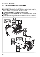
Page 20: ...hem with a solution made of water and detergent Do not use fuel petrol or solvents q If the plates are damaged ask for new ones to Komatsu or to your Komatsu Dealer q In case of replacement of a compo...

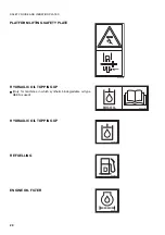
Page 21: ...ey look like and their respective meanings WORK IN PROGRESS q Do not approach or stand within the equipment operating range when the boom and the bucket are raised DO NOT OPEN THE ENGINE HOOD q Do not...

Page 22: ...M LIFTING SAFETY PLATE HYDRAULIC OIL TOPPING UP q Only for machines in which synthetic biodegradable oil type HEES is used HYDRAULIC OIL TOPPING UP REFUELLING ENGINE OIL FILTER RKA01380 22L 98 R2390 R...

Page 23: ...Y NOISE AND VIBRATION PLATES 21 FUEL FILTER ENGINE AIR INTAKE FILTER ENGINE COOLANT ENGINE COOLANT PRESSURE HYDRAULIC OIL LEVEL HYDRAULIC OIL FILTER D RWA00060 RWA00090 RWA00130 RWA00110 RWA00100 RWA0...

Page 24: ...SAFETY NOISE AND VIBRATION PLATES 22 POWER OUTLET ANCHORAGE POINT LIFTING POINT 12 V RWA00120 RWA00200 RWA04920...

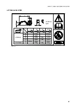
Page 25: ...ION PLATES 23 LIFTING CAPACITIES RKA16650 A B W L 20W 98 91510 2m 3m 1m 0 1m 0 L 965mm L 1210mm 310kg 285kg 300kg 280kg 275kg 165kg 150kg 310kg 170kg 140kg 280kg 155kg 145kg 195kg 125kg A B 2m 3m MAX...

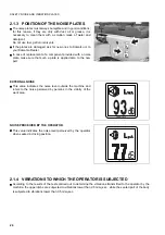
Page 26: ...plate is applied also to the new part EXTERNAL NOISE q This value indicates the noise level outside the machine and refers to the noise perceived by persons in the vicinity of the work area NOISE PERC...

Page 27: ...m in good operating conditions q Any improper use of the safety devices may result in serious injury or even death 2 2 3 CLOTHING AND PERSONAL PROTECTION ITEMS q Do not wear large or loose clothes rin...

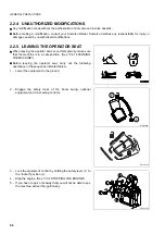
Page 28: ...ake sure that the machine is in a safe position See 2 4 14 PARKING THE MACHINE q Before leaving the operator seat carry out the following operations in the sequence indicated below 1 Lower the equipme...

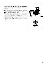
Page 29: ...e very carefully q Do not hold or rest on the control levers q Both when getting on and when getting off the machine always maintain three points of contact holding or resting points in order to avoid...

Page 30: ...ng oil tighten the fuel or oil cap securely q Do not fill the tank completely in order to leave room for the fuel to expand q In case some fuel is spilled wipe it up immediately 2 2 8 PREVENTING BURNS...

Page 31: ...This as a preview PDF file from best manuals com Download full PDF manual at best manuals com...

Reviews: